Frame-Based Video Pipeline Using Zynq UltraScale+ and USB Camera
This example shows how to design and deploy a frame-based video processing pipeline implemented in Simulink® on a Zynq® UltraScale+ device.
This example uses SoC Blockset™ Support Package for AMD® FPGA and SoC Devices to deploy the Frame-Based Video Pipeline in Simulink example to the Xilinx Zynq® UltraScale+ MPSoC ZCU106 Evaluation Kit. The workflow can also be applied to other frame-based Vision HDL Toolbox examples.
This example uses a USB Camera to capture the input video to the hardware. For a frame-based example that uses the HDMI Input, see Frame-Based Video Pipeline Using Zynq UltraScale+ and FMC-HDMI-CAM.
Set Up Hardware
Before running this example, you must install SoC Blockset™ Support Package for AMD® FPGA and SoC Devices and run the guided hardware setup included in the support package installation. The setup tool configures the target board and host machine, confirms that the target starts correctly, and verifies host-target communication.
For more information, see Install Support for AMD FPGA and SoC Devices (SoC Blockset) and Set Up AMD FPGA and SoC Devices (SoC Blockset).
Model Frame-Based Algorithm
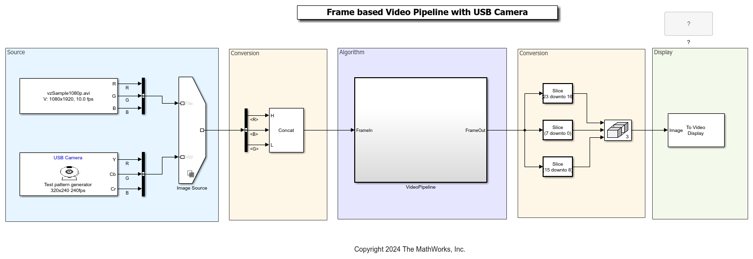
This model provides a frame-based implementation of the algorithm for targeting HDL. You can run this simulation without hardware as the video source for this example comes from the From Multimedia File block, that reads video data from a multimedia file.
open_system('soc_video_frame_pipeline')

The example model simulates a frame-based design. When you generate HDL code for this function with HDL Coder™ tools and frame-to-sample optimization, the generated code implements a hardware-friendly streaming video interface. To enable frame-to-sample conversion for this model, set these Configuration properties
hdlset_param('soc_video_frame_pipeline','FrameToSampleConversion','on');
hdlset_param('soc_video_frame_pipeline/VideoPipeline/FrameIn','ConvertToSamples','on');
Algorithms are often sensitive to the specific video input. You can also run the model with real-world data coming from the USB camera by configuring the Image Source block accordingly. To do this, right-click on the variant selection icon in the lower-left corner of the Image Source block, choose Label mode active choice, and select HW.
Target the Frame-Based Algorithm
In preparation for targeting, set up the EDA tool chain. For example:
hdlsetuptoolpath('ToolName','Xilinx Vivado','ToolPath','C:\Xilinx\Vivado\2023.1\bin\vivado.bat');
For more information, see hdlsetuptoolpath (HDL Coder).
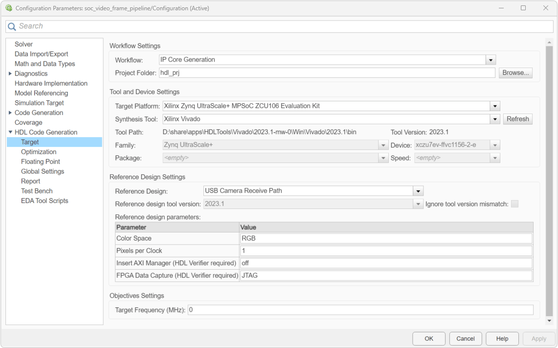
Once you are satisfied with the frame-based model simulation results, you can target the algorithm to the FPGA on the Zynq UltraScale+ board. In the Simulink Toolstrip, in the Apps tab, select HDL Coder. In the HDL Code tab, select Settings. In the Workflow settings, set the Workflow to IP Core Generation, Target Platform to Xilinx Zynq UltraScale+ MPSoC ZCU106 Evaluation Kit. In the Reference design settings, set the Reference Design to USB Camera Receive Path. This example uses RGB Color Space and 1 sample per clock. So set the parameter Color Space to RGB and Pixels per Clock to 1. Other supported values for Color Space is YCbCr.

In the HDL Code tab, select Target Interface. The input frame port for which frame-to-samples is enabled must be mapped to AXI4-Stream Video Slave and the output port must be mapped to AXI4-Stream Video Master.

Validate the interface mapping, then click on Build Bitstream in the HDL Code tab. This step generates the bitstream in an external shell.
Once the bitstream is generated, you can download it in the Simulink Toolstrip. In the HDL Code tab, select Build Bitstream > Program Target Device.
To download the bitstream at a later stage, use these commands to create hardware object and deploy the bitstream and device tree to the hardware.
  hw = socHardwareBoard('Xilinx Zynq UltraScale+ MPSoC ZCU106 Evaluation Kit','hostname','192.168.1.101','username','root','password','root');
  programFPGA( hw , "PROJECT_FOLDER\vivado_ip_prj\vivado_prj.runs\impl_1\design_1_1ppc_wrapper.bit", "devicetree_usb_camera_1ppc.dtb");
Using Generated Interface models
To generate the interface model, in the Simulink Toolstrip, in the HDL Code tab, select Build Bitstream > Software Interface Model. This will create a Host IO model and a software interface model. In the Host IO model, you can connect the output of the Video Capture USB block to a To Video Display block and visualize the output.
In the software interface model, you must select the input video resolution that matches the model that you generated code from.