Single-Phase Energization of a Three-Phase Line
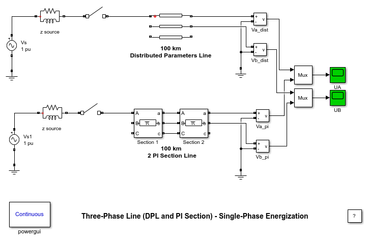
This example shows transients obtained with a distributed parameter line model and a PI section line model.
G. Sybille (Hydro-Quebec)

Description
A 100 km, three-phase line is energized on a 735 kV, 30,000 MVA equivalent network. The line is first energized on phase A at t = 1/4 cycle (maximum of source voltage) and then deenergized at t = 4 cycles. Phase B and phase C are left open. Switchings are performed simultaneously on two different line models:
- Distributed parameters line
- Three-phase PI section line consisting of two 50 km sections
Voltages obtained on phases A and B at the line receiving end with the two models are compared.
Simulation
Open the two scopes and start the simulation. Compare the voltages obtained on phase A and phase B (induced voltage) with the two models. Zoom on voltages right after energizing and notice the sharp edges obtained with the distributed parameter line (yellow trace). These voltage steps which are due to travelling wave reflections at both ends of the line are filtered by the PI model. Notice also that phases A and B stay charged at peak voltage when the breakers are opened.