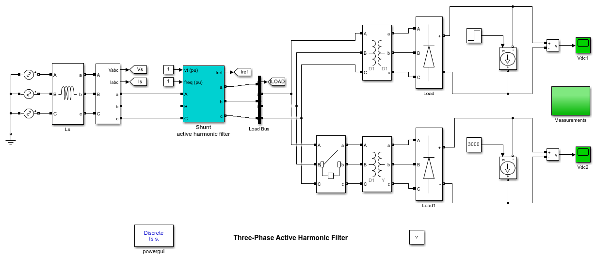
Three-Phase Active Harmonic Filter
This example shows the use of a shunt active harmonic filter (AHF) to minimize the harmonic content propagated to the source from a non-linear load.
Graham Dudgeon, Senior Consultant, The MathWorks, Inc.

Description
The circuit models a standard shunt AHF with IGBT inverter and series inductor on the AC side and DC capacitor energization. The load consists of two diode rectifiers which are phase-shifted by 30 degrees. The Delta-Y connected rectifier is connected after 10 cycles to change the load from 6-pulse to 12-pulse.
The AHF uses a PLL to generate a reference sinusoidal source current which is in-phase and has the same RMS gain as the load current. The current error between the load current and the reference current is generated by the IGBT Bridge through hysteresis switching. The AHF aims to inject this current error at the point of common coupling in order to match the source current as closely as possible with the reference current.
Simulation
Start the simulation. You can observe phase A reference and source current on scope 'Iref_Isource' and phase A source and load current on scope 'Isource_Iload'. If you look under the mask of the AHF, further responses specific to the operation of the AHF are available.
At t=0s, only the delta/delta connected diode rectifier is in-circuit. The DC current is set at 2000A. Observe from 'Iref_Isource' that the AHF captures the reference current within 1 cycle.
FFT Analysis tool of Powergui show an FFT analysis of the load and source phase A current on the 3rd cycle. It is seen that the AHF has effectively reduced the THD from 22.41% to 0.69%.
At t=5/60s, the DC current is increased from 2000A to 3000A. Observe that the AHF effectively responds to this change in load and captures the new reference current within one cycle.
At t=10/60s, the delta/wye diode rectifier is connected, thus producing a 12-pulse load. Observe that the AHF again captures the new reference current within one cycle. FFT Analysis tool of Powergui shows the load and source phase A current on the 13th cycle. It is seen that the AHF has effectively reduced the THD from 4.80% to 0.93%.
Notes
The circuit has been discretized with a 2us time step. This time step may be increased but a decrease in accuracy of the simulation will be observed.