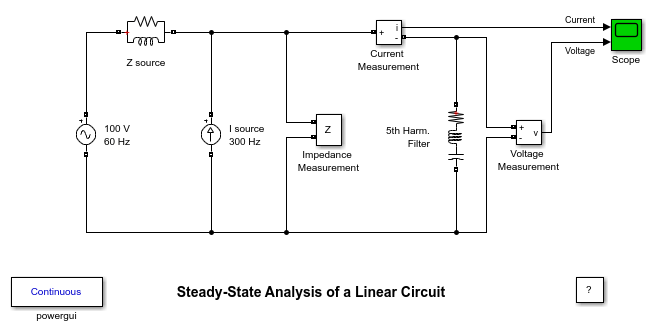
선형 회로의 정상 상태 분석
이 예제에서는 선형 전기 회로의 정상 상태 동작을 분석하기 위해 Powergui 블록과 Impedance Measurement 블록을 사용하는 방법을 보여줍니다.
G. Sybille(Hydro-Quebec)

설명
5차 고조파 필터가 60Hz, 100V 유도성 소스를 통해 전력이 공급되는 부스바에 연결됩니다. 5차 고조파(300Hz, 1A) 전류가 부스바에 주입됩니다.
이 선형 시스템은 3개의 상태(2개의 인덕터 전류와 1개의 커패시터 전압), 2개의 입력(Vs와 Is), 2개의 출력(전류 측정값과 전압 측정값)으로 구성됩니다.
Impedance Measurement 블록은 회로의 임피던스 대 주파수를 계산하는 데 사용됩니다.
시뮬레이션
1. Powergui 블록을 사용하여 전압 페이저와 전류 페이저의 정상 상태 60Hz 성분과 300Hz 성분을 찾습니다. 3개 상태의 값(페이저와 초기값) 또한 Powergui 블록에서 얻을 수 있습니다.
2. 스코프를 열고 "시뮬레이션/시작" 메뉴에서 시뮬레이션을 시작합니다. 시뮬레이션은 정상 상태에서 시작됩니다. Powergui 블록을 사용하여 "Impedance vs Frequency Measurement"를 선택합니다. 새 창이 열립니다.
3. 지정된 주파수 범위 벡터 [0: 2:1000](2Hz 스텝으로 0~1000Hz)에서 측정이 수행됩니다. "Display" 버튼을 클릭합니다. 그래픽 창에 임피던스가 표시됩니다. 필터의 조정된 주파수에 해당하는 300Hz에서의 직렬 공진을 관찰합니다.