Model Transmission System Using Delta Reference (Three-Phase) Block
This example shows how to use a Delta Reference (Three-Phase) block to provide a reference point for delta winding in a simple model of a transmission system.
Why Use a Delta Reference (Three-Phase) Block
This figure shows a transmission system that contains a three-phase AC voltage source, a wye-delta transformer, a delta-wye transformer, and a wye-connected load.
![]()
In this transmission system, the Voltage Source (Three-Phase) block generates the required voltage for the distribution. The wye-delta transformer and the delta-wye transformers step up and step down this voltage, respectively.
You can model the transformers with Two-Winding Transformer (Three-Phase) blocks. To model the wye-delta transformer, set the Winding 1 connection type parameter to Wye with floating neutral and the Winding 2 connection type parameter to Delta 1 o'clock. To model the delta-wye transformer, set the Winding 1 connection type parameter to Delta 1 o'clock and the Winding 2 connection type parameter to Wye with floating neutral.
In a wye connection, you connect three conductors at a neutral point in a "Y" shape. You can also connect a ground to the neutral point. Wye connections are suitable for use on the distribution side, which requires a three-phase, four-wire system with a ground for safety. In a delta connection, you connect three conductors in a closed triangle. You can therefore use delta connections for high-voltage overhead transmission when you do not require the neutral wire for safety and you want to reduce the cost by using only three wires. Delta windings also provide better fault tolerance because the load voltage and current remain constant if one of the windings fails.
If you simulate the transmission system shown in the figure, you receive this error message:
![]()
The exact error message depends on the values you select for the parameters of the blocks.
The warning message explains that the model does not provide enough information to solve for values of some variables.
![]()
To resolve this error, connect a Delta Reference (Three-Phase) block between the two transformers in a delta-winding configuration. The line-line vector voltages form a closed triangle. The Delta Reference (Three-Phase) block represents the centre of this triangle. This reference gives the model enough information to solve for the values of all of its variables.
Model Overview
Open the ee_delta_transmission model.
myModel = "ee_delta_transmission";
open_system(myModel)![]()
The complete model contains a Delta Reference (Three-Phase) block between the wye-delta transformer and delta-wye transformer.
Simulate the model. The simulation runs without errors because the model calculates the absolute node voltages relative to the voltage at the reference point.
sim(myModel);
Plot the Results
Extract the voltage from both windings of the delta-wye transformer.
voltage_delta = simlog_ee_delta_transmission.Delta_Wye_Transformer.N1.V.series.values;
voltage_wye = simlog_ee_delta_transmission.Delta_Wye_Transformer.N2.V.series.values;
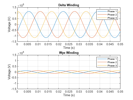
Plot the results. The delta-wye transformer steps down the voltage from 115kV for high-voltage transmission to 13kV for low-voltage distribution.
ee_delta_transmission_plot(tout,voltage_delta,voltage_wye)
See Also
Delta Reference (Three-Phase) | Two-Winding Transformer (Three-Phase)