Wind Turbine (Mechanical)

Libraries:
Simscape /
Electrical /
Electromechanical
Description
The Wind Turbine (Mechanical) block represents a wind turbine that converts the kinetic energy of the wind into mechanical power. The power of the turbine depends on the nondimensional power coefficient Cp. You can tabulate this coefficient with blade pitch angle and tip speed ratio by specifying the Power coefficient table, Cp(β,TSR) parameter.
The values at the physical signal ports V and β represent the wind speed and the collective blade pitch. Port R models the mechanical rotational conserving port associated with the shaft.
Equations
The block calculates the coefficients of power by using a table lookup such that
where:
βRef is the reference pitch angle.
λRef is the reference tip speed ratio.
CP,Ref is the Power coefficient table parameter.
λSmooth is the smoothed tip speed ratio.
The block uses this equation as the basis for the instantaneous tip speed ratio
where:
R is the Turbine radius parameter.
ɷ is the differential angular velocity between the shaft and the case.
V is the incident air velocity on the rotor. This value is the physical signal input port V.
The block uses this equation to describe the smoothed version of the instantaneous tip speed ratio equation
where VThr is the Wind speed threshold parameter. The block uses this equation as a basis for the power
where:
ρ is the Air density parameter.
A is the area of the circle swept by the turbine blades, and A = πr2.
To relate the block parameters to the wind turbine mechanical power rating, determine the wind turbine power at the peak power coefficient and the rated wind speed. The rated power corresponds to the block parameters using the equation
where:
CP,max is the peak power coefficient. This is the maximum value in the Power coefficient table, Cp(β,TSR) parameter.
Vrated is the rated wind speed. Rated wind speeds are typically 10 to 15 m/s. The designs of wind turbine controller can alter strategy at this wind speed to maintain the rated power.
A is the rotor swept area, where A = πr2.
The block uses numerically smoothed equations for the power, such that
Variables
To set the priority and initial target values for the block variables before simulation, use the Initial Targets section in the block dialog box or Property Inspector. For more information, see Set Priority and Initial Target for Block Variables.
Use nominal values to specify the expected magnitude of a variable in a model. Using system scaling based on nominal values increases the simulation robustness. Nominal values can come from different sources. One of these sources is the Nominal Values section in the block dialog box or Property Inspector. For more information, see System Scaling by Nominal Values.
Examples

Model a Wind Power System with a Simplified Generator
Model a low-fidelity, three-phase, grid-connected wind power system by using a Simplified Generator block. Use this low-fidelity electrical model for planning and pitch control studies.

Wind Turbine
Model, parameterize, and test a wind turbine with a supervisory, pitch angle, MPPT (maximum power point tracking), and derating control. When you run the plot function, it generates a plot of the state transitions, normalized physical quantities such as the wind speed, wind turbine rotation speed, generator power, and pitch angle.
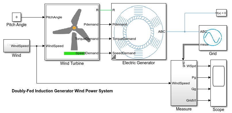
Model Doubly-Fed Induction Generator Wind Power System
Model a doubly-fed induction generator (DFIG)-based, three-phase, grid-connected wind power system. The DFIG-based, or type 3, electrical system is one of the most-used control schemes for extracting electrical energy from a wind turbine.
Assumptions and Limitations
The block generates power only for positive angular velocities.
Ports
Inputs
Conserving
Parameters
Extended Capabilities
Version History
Introduced in R2023a