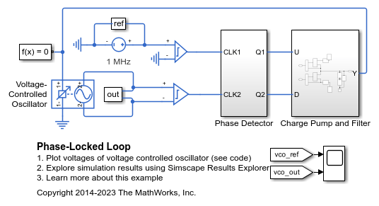
Voltage-Controlled Oscillator
Behavioral model of voltage-controlled oscillator
Libraries:
Simscape /
Electrical /
Integrated Circuits
Description
The Voltage-Controlled Oscillator block provides a behavioral model of a voltage-controlled oscillator (VCO). The output voltage is defined by the following equations:
where:
vin is the voltage applied across the 1+ and 1– ports.
vout is the voltage across the 2+ and 2– ports.
fnom is the oscillator frequency when the input control voltage is vnom.
F is a linear function of vlim or a lookup table function of vlim.
A is the output voltage peak amplitude.
t is simulation time.
iout is the output current.
Rout is the output resistance.
If you choose Linear for the Frequency dependence
on input voltage parameter, then the function F is
given by:
where k is the rate of change of frequency with input voltage.
If you choose Tabulated for the Frequency
dependence on input voltage parameter, then the function
F is defined by the vectors of input voltages and corresponding
output frequency deviations from nominal that you supply. The values for
vmin and
vmax are the first and the last values of
the input voltage vector.
You can model the time delay between a change in the input control voltage and the oscillator frequency. Do this by modeling a first-order dynamic between vlim and the value passed to the function F.
Examples
Ports
Conserving
Parameters
Extended Capabilities
Version History
Introduced in R2013b

