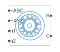
PMSM (Six-Phase)
정현파 플럭스 분포를 갖는 6상 영구 자석 동기 모터
라이브러리:
Simscape /
Electrical /
Electromechanical /
Permanent Magnet
설명
PMSM (Six-Phase) 블록은 6상 스타 권선 고정자가 있는 PMSM(영구 자석 동기기)을 모델링합니다. 이 블록을 사용하여 고정자 권선이 6개인 모터, 즉 IPMSM(매립형 영구 자석 동기기), SPMSM(표면형 영구 자석 동기기), 축자속(팬케이크) 모터 또는 PMSM 서보모터를 모델링할 수 있습니다.
6상 PMSM은 ABC 그룹과 XYZ 그룹이라는 두 개의 3상 고정자 권선 그룹으로 구성됩니다. 이 두 그룹은 30도의 위상 변위를 가집니다.
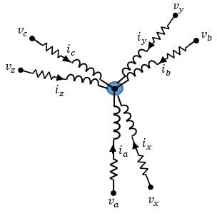
다음 그림은 고정자 권선에 대한 등가 전기 회로를 보여줍니다.
방정식
고정자 권선 양단 간의 전압은 다음과 같습니다.
여기서 각각은 다음과 같습니다.
va, vb, vc는 포트 ~ABC에서 중성점 포트 n1까지의 개별 상 전압입니다.
vx, vy, vz는 포트 ~XYZ에서 중성점 포트 n2까지의 개별 상 전압입니다.
Rs는 각 고정자 권선의 등가 저항입니다.
ia, ib, ic는 포트 ~ABC에서 포트 n1로 흐르는 전류입니다.
ix, iy, iz는 포트 ~XYZ에서 포트 n2로 흐르는 전류입니다.
, , , , , 는 각 고정자 권선에서의 자기 플럭스의 변화율입니다.
영구 자석과 6개의 권선은 각 권선과 쇄교하는 총 플럭스에 영향을 미칩니다. 총 플럭스는 다음과 같습니다.
여기서 각각은 다음과 같습니다.
ψa, ψb, ψc, ψx, ψy, ψz는 각 고정자 권선과 쇄교하는 총 플럭스입니다.
Laa, Lbb, Lcc, Lxx, Lyy, Lzz는 고정자 권선의 자체 인덕턴스입니다. 이러한 자체 인덕턴스는 회전자 전기각 θe의 함수이며, 고정자 1상당 자체 인덕턴스 Ls와 고정자 인덕턴스 변동 Lm에 따라 달라집니다.
입니다. 여기서 θr은 회전자 기계각입니다.
rotor offset은 d축을 기준으로 회전자 전기각을 정의하는 경우
0이고 q축을 기준으로 회전자 전기각을 정의하는 경우-pi/2입니다.Ls는 고정자 1상당 자체 인덕턴스입니다. 이 값은 고정자 권선 각각의 평균 자체 인덕턴스입니다.
Lm은 고정자 인덕턴스 변동입니다. 이 값은 회전자 각도의 변화에 따라 자체 인덕턴스와 상호 인덕턴스가 변동하는 양입니다.
Lab, Lac, Lba 등은 고정자 권선의 상호 인덕턴스입니다. 이러한 상호 인덕턴스는 회전자 전기각 θe의 함수이며, 고정자 상호 인덕턴스 Ms와 고정자 1상당 자체 인덕턴스 Ls에 따라 달라집니다.
Ms는 고정자 상호 인덕턴스입니다. 이 값은 고정자 권선 간의 평균 상호 인덕턴스입니다.
ψam, ψbm, ψcm, ψxm, ψym, ψzm은 고정자 권선과 쇄교하는 영구 자석 플럭스입니다.
권선 a-a'와 쇄교하는 영구 자석 플럭스는 θe = 0°일 때 최대이고 θe = 90°일 때 0입니다. 따라서 쇄교하는 모터 플럭스는 다음으로 정의됩니다.
여기서 ψm은 영구 자석 쇄교 자속입니다.
단순화된 전기 방정식
분리 변환(decoupled transformation)을 블록 전기 방정식에 적용하면 회전자 각도와 무관한, 토크에 대한 표현식이 생성됩니다.
분리 변환은 다음으로 정의됩니다.
변환 행렬 P는 다음과 같은 의사 직교 속성을 갖습니다.
고정자 권선 전압 및 전류에 대해 분리 변환을 사용하면 이러한 전압 및 전류는 다음과 같이 회전자 각도에 독립적인 dq0 프레임으로 변환됩니다.
ABC 그룹과 XYZ 그룹에 대한 d축, q축, 영상 성분 고정자 전압과 쇄교 자속을 얻으려면 전압과 쇄교 자속 방정식에 변환을 적용합니다.
여기서 각각은 다음과 같습니다.
vd, vq, vz1, vz2, v01, v02는 ABC 그룹과 XYZ 그룹에 대한 d 성분, q 성분, z1 성분, z2 성분과 영상 성분 고정자 전압이며 다음과 같이 정의됩니다.
id, iq, iz1, iz2, i01, i02는 ABC 그룹과 XYZ 그룹에 대한 d축, q축, 영상 성분 고정자 전류이며 다음과 같이 정의됩니다.
은 고정자 d축 인덕턴스입니다.
은 고정자 q축 인덕턴스입니다.
는 고정자 영상 성분 인덕턴스입니다.
ω는 회전자의 회전 기계 속도입니다.
N은 회전자 영구 자석 극쌍 개수입니다.
토크 방정식은 다음과 같이 정의됩니다.
열 효과 모델링
전력을 열로 변환하는 손실의 효과를 모델링하기 위해 열 포트를 노출할 수 있습니다. 열 포트를 노출하려면 모델링 옵션 파라미터를 다음 중 하나로 설정합니다.
열 포트 없음— 블록이 고정자 권선과 연결되는 확장 전기 에너지 보존 포트를 포함하지만 열 포트는 포함하지 않습니다.열 포트 표시— 블록이 각각의 권선과 회전자에 대해 고정자 권선 및 열 에너지 보존 포트와 연결되는 확장 전기 에너지 보존 포트를 포함합니다.
액추에이터 블록에서의 열 포트 사용에 대한 자세한 내용은 Simulating Thermal Effects in Rotational and Translational Actuators 항목을 참조하십시오.
변수
시뮬레이션 전에 블록 변수의 우선 순위와 초기 목표값을 설정하려면 블록 대화 상자 또는 속성 인스펙터에서 초기 목표값 섹션을 사용합니다. 자세한 내용은 Set Priority and Initial Target for Block Variables 항목을 참조하십시오.
공칭 값은 모델에서 변수의 예상 크기를 지정하는 방법을 제공합니다. 공칭 값을 기반으로 시스템 스케일링을 사용하면 시뮬레이션 강인성이 향상됩니다. 블록 대화 상자 또는 속성 인스펙터에서의 공칭 값 섹션을 비롯한 다른 소스를 사용하여 공칭 값을 지정할 수 있습니다. 자세한 내용은 System Scaling by Nominal Values 항목을 참조하십시오.
예제
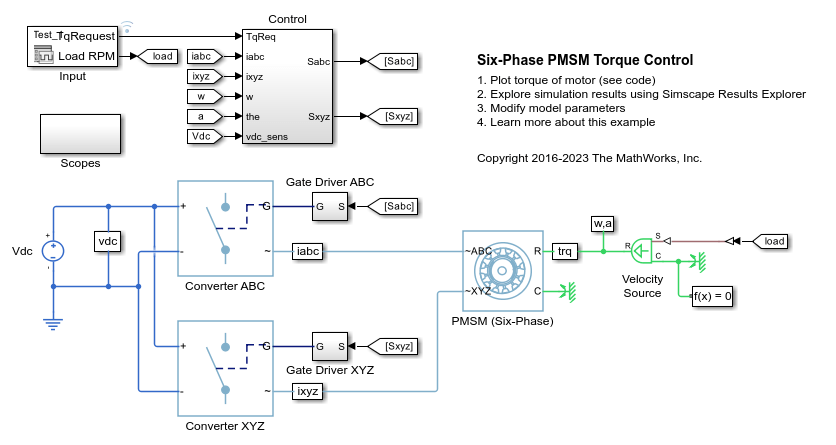
6상 PMSM 토크 제어
이 예제에서는 6상 영구 자석 동기기(PMSM) 기반 전기-견인 드라이브에서 토크를 제어하는 방법을 보여줍니다. DC 전압원이 2개의 제어된 3상 컨버터를 통해 PMSM에 전력을 공급합니다. PMSM은 부하에 따라 모터 모드와 발전기 모드 모두에서 작동합니다. 이상적 각속도 소스가 부하를 제공합니다. Control 서브시스템은 개루프 접근법을 사용하여 토크를 제어하고 폐루프 접근법을 사용하여 전류를 제어합니다. 각 샘플 시점에 토크 요청은 관련된 q축 전류 기준으로 변환됩니다. 전류 제어는 PI 기반입니다. 시뮬레이션은 모터 모드와 발전기 모드 모두에서 몇 가지 토크 스텝을 사용합니다. Scopes 서브시스템은 시뮬레이션 결과를 확인할 수 있는 스코프를 포함합니다.
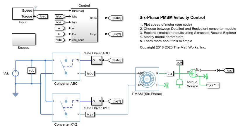
6상 PMSM 속도 제어
이 예제에서는 6상 영구 자석 동기기(PMSM) 기반 전기-견인 드라이브의 회전자 각속도를 제어하는 방법을 보여줍니다. DC 전압원이 2개의 제어된 3상 컨버터를 통해 PMSM에 전력을 공급합니다. PMSM은 부하에 따라 모터 모드와 발전기 모드 모두에서 작동합니다. 이상적 토크 소스가 부하를 제공합니다. Scopes 서브시스템은 시뮬레이션 결과를 확인할 수 있는 스코프를 포함합니다. Control 서브시스템은 바깥쪽의 각속도 제어 루프 1개와 안쪽의 전류 제어 루프 4개를 갖는 PI 기반 캐스케이드 제어 구조를 포함합니다. 1초의 시뮬레이션 중에 각속도 요구량은 0rpm, 500rpm, 2000rpm, 그런 다음 3000rpm입니다.
포트
보존
파라미터
참고 문헌
[1] Krause, Paul, Oleg Wasynczuk, Scott Sudhoff, and Steven Pekarek, eds. Analysis of electric machinery and drive systems. Hoboken, NJ, USA: John Wiley & Sons, Inc., 2013. https://doi.org/10.1002/9781118524336.
[2] Su, Jian Yong, Jin Bo Yang, and Gui Jie Yang. Research on Vector Control and PWM Technique of Six-Phase PMSM. Advanced Materials Research 516–517 (May 2012): 1626–31. https://doi.org/10.4028/www.scientific.net/AMR.516-517.1626.
확장 기능
버전 내역
R2020b에 개발됨