Building Your Own Drive
Introduction
The following information describes how to build a motor drive model using Simulink® and Simscape™ Electrical™ Specialized Power Systems blocks. You will build the field-oriented-control motor drive, very similar to the AC3 model. The following figure shows the block diagram of the drive.
Field-Oriented Variable-Frequency Induction Motor Drive
Description of the Drive
The induction motor is fed by a current-controlled PWM inverter, which operates as a three-phase sinusoidal current source. The motor speed ω is compared to the reference ω* and the error is processed by the speed controller to produce a torque command Te*.
As shown below, the rotor flux and torque can be separately controlled by the stator direct-axis current ids and quadrature-axis current iqs, respectively.
Field-Oriented Control Principle
The stator quadrature-axis current reference iqs* is calculated from torque reference Te* as
where Lr is the rotor inductance, Lm is the mutual inductance, and |ψr|est is the estimated rotor flux linkage given by
where τr = Lr / Rr is the rotor time constant.
The stator direct-axis current reference ids* is obtained from rotor flux reference input |ψr|*.
The rotor flux position Θe required for coordinates transformation is generated from the rotor speed ωm and slip frequency ωsl.
The slip frequency is calculated from the stator reference current iqs* and the motor parameters.
The iqs* and ids* current references are converted into phase current references ia*, ib*, ic* for the current regulators. The regulators process the measured and reference currents to produce the inverter gating signals.
The role of the speed controller is to keep the motor speed equal to the speed reference input in steady state and to provide a good dynamic during transients. The controller can be a proportional-integral type.
Modeling the Induction Motor Drive
Open the power_acdrive model
and save it as case3 in your working directory so that you can
make further modifications without altering the original file.
The next figure shows the power_acdrive model in which blocks from
Simscape
Electrical Specialized Power Systems and Simulink libraries are used to model the induction motor drive.
Vector Control of AC Motor Drive (power_acdrive)
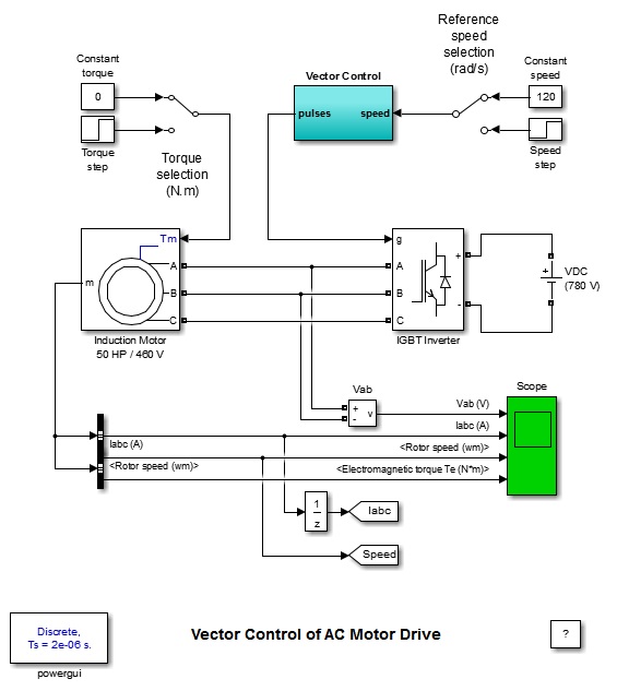
The induction motor is modeled by an Asynchronous Machine block. The motor used in this case study is a 50 HP, 460 V, four-pole, 60 Hz motor having the following parameters:
Rs |
|
Lls |
|
Lm |
|
Rr |
|
Llr |
|
The reference speed and the load torque applied to the motor shaft can be both selected by a Manual Switch block in order to use either a constant value or a step function. Initially the reference speed is set to a constant value of 120 rad/s and the load torque is also maintained constant at 0 N.m
The field-oriented control is modeled by the Vector Control block, as shown in Vector Control of AC Motor Drive (power_acdrive). This block consists of Simulink blocks shown in the following figure.
Vector Control Block
The IGBT inverter is modeled by a Universal
Bridge block in which the Power Electronic device and Port
configuration options are selected as IGBT/Diode and ABC as
output terminals respectively. The DC link input voltage is represented
by a 780 V DC voltage source.
The current regulator consists of three hysteresis controllers and is built with Simulink blocks. The motor currents are provided by the measurement output of the Asynchronous Machine block.
The conversions between abc and dq reference frames are executed by the abc_to_dq0 Transformation and dq0_to_abc Transformation blocks
abc_dq
dq_abc

The rotor flux is calculated by the Flux_Calculation block.
The rotor flux position (Θe) is calculated by the Teta Calculation in Vector Control Block. The motor speed is provided by the measurement output of the Asynchronous Machine block.

The stator quadrature-axis current reference (iqs*) is calculated by the iqs*_Calculation block.
The stator direct-axis current reference (ids*) is calculated by the id*_Calculation block.

The speed controller is of proportional-integral type and is implemented using Simulink blocks.

Simulating the Induction Motor Drive
In order to increase simulation speed, this model is discretized
using a sample time of 2 µs. The variable Ts = 2e-6 automatically
loads into your workspace when you open this model. This sample time
Ts is used both for the power circuit (Ts specified
in the Powergui) and the control system.
Run the simulation.
The motor voltage and current waveforms as well as the motor speed and torque are displayed on four axes of the scope connected to the variables Vab, Iabc, ωm, and Te.
Starting the Drive
You can start the drive by specifying [1,0,0,0,0,0,0,0] as
the initial conditions for the Asynchronous
Machine block (initial slip = 1 and no currents flowing in
the three phases). The speed reference is 120 rad/s.
The motor speed, electromechanical torque, and currents observed during the starting of the induction motor drive are shown in Starting the Induction Motor Drive.
Note that you can save the final system state vector and use it as the initial state in a subsequent simulation so that the simulation can start under steady-state conditions.
Starting the Induction Motor Drive
Steady-State Voltage and Current Waveforms
When the steady state is attained, you can stop the simulation and zoom on the scope signals.
This figure shows the motor voltage, current, and torque waveforms obtained when the motor is running at no load (torque = 0 N.m) at a speed of 120 rad/s.
The 20 A band imposed by the hysteresis current regulator is clearly seen on the three motor currents.
Steady-State Motor Current, Voltage, and Torque Waveforms

Speed Regulation Dynamic Performance
You can study the drive dynamic performance (speed regulation performance versus reference and load torque changes) by applying two changing operating conditions to the drive: a step change in speed reference and a step change in load torque.
Use the Reference Speed selection switch and the Torque selection switch to set speed
reference steps from 120 rad/s to 160 rad/s at t = 0.2 s and the load torque steps
from 0 N.m to 200 N.m at t = 1.8 s. The final state vector obtained with the
previous simulation can be used as the initial condition so that the simulation
starts from steady state. Load the power_acdrive_init.mat
file, which creates the xInitial variable.
In the Simulation tab, click Model
Settings. Select Data Import/Export. Select
Initial state and then click OK.
Restart the simulation.
The response of the induction motor drive to successive changes in speed reference and load torque is shown here.
Dynamic Performance of the Induction Motor Drive

References
[1] Leonhard, W., Control of Electrical Drives, Springer-Verlag, Berlin, 1996.
[2] Murphy, J. M. D., and Turnbull, F. G., Power Electronic Control of AC Motors, Pergamon Press, Oxford, 1985.
[3] Bose, B. K., Power Electronics and AC Drives, Prentice-Hall, Englewood Cliffs, N.J., 1986.
You can also select a web site from the following list:
Americas
- América Latina (Español)
- Canada (English)
- United States (English)
Europe
- Belgium (English)
- Denmark (English)
- Deutschland (Deutsch)
- España (Español)
- Finland (English)
- France (Français)
- Ireland (English)
- Italia (Italiano)
- Luxembourg (English)
- Netherlands (English)
- Norway (English)
- Österreich (Deutsch)
- Portugal (English)
- Sweden (English)
- Switzerland
- United Kingdom (English)