Modify a Drive Block
If you have to change electrical connections or control modules, you can do so by modifying a
drive block. The following example uses ac6_example to replace the
three-phase electric source by a battery. To modify a drive block:
Break the Link of the Drive Block
Open the ac6_example by typing
ac6_examplein the MATLAB® Command window. The drive is fed by a three-phase voltage source.Simulate the model (in accelerator mode) and observe the results.
Break the link between the drive block and its library.
Right-click the block, and then select Library Link > Disable Link.
Right-click the block again, and then select Library Link > Break Link.
Modify the Drive Block
Right-click the drive block and select Mask > Look Under Mask.
Delete the three-phase electrical connections, the diode rectifier, and the braking chopper.
Right-click the Permanent Magnet Synchronous Machine block and select Mask > Look Under Mask. Select the A and B Connection Port block, and copy them to the top-level model. Connect the blocks to the positive and negative terminals of the Three-Phase Inverter block. Add a Simulink® Ground block and connect it to the output port Conv.
Use the Customized Drive Block
Save the model as
ac6_example2.In the diagram, delete the three-phase source. Replace it with a 300Vdc/1Ah/NiMH Battery block and a 100 µF capacitor block connected in parallel.
Connect the Conv output of the block to a Terminator block. Remove the DC bus voltage blocks that are in the Demux block.
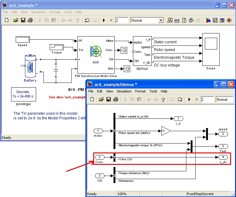
Add a Bus Selector block and then select the Voltage (V) bus signal coming from the
moutput of the Battery block.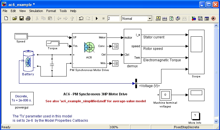
You can also select a web site from the following list:
Americas
- América Latina (Español)
- Canada (English)
- United States (English)
Europe
- Belgium (English)
- Denmark (English)
- Deutschland (Deutsch)
- España (Español)
- Finland (English)
- France (Français)
- Ireland (English)
- Italia (Italiano)
- Luxembourg (English)
- Netherlands (English)
- Norway (English)
- Österreich (Deutsch)
- Portugal (English)
- Sweden (English)
- Switzerland
- United Kingdom (English)