Worm and Gear Constraint
Kinematic constraint between worm and gear bodies with perpendicular non-intersecting rotation axes

Libraries:
Simscape /
Multibody /
Gears and Couplings /
Gears
Description
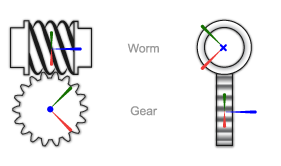
The Worm and Gear Constraint block represents a kinematic constraint between worm and gear bodies held at a right angle. The base frame port identifies the connection frame on the worm and the follower frame port identifies the connection frame on the gear. The rotation axes coincide with the connection frame z-axes. The worm and gear rotate at a fixed velocity ratio determined by the gear pitch radii or tooth-thread ratio.
The worm thread direction can follow either right-hand or left-hand conventions. The convention used determines the relative directions of the worm and gear rotational velocities. A right-hand convention causes the worm and gear to rotate in the same direction about the respective z-axes. A left-hand convention causes the worm and gear to rotate in opposite directions instead.
The block represents only the kinematic constraint characteristic to a worm-and-gear system. Gear inertia and geometry are solid properties that you must specify using solid blocks. The gear constraint model is ideal. Backlash and gear losses due to Coulomb and viscous friction between teeth are ignored. You can, however, model viscous friction at joints by specifying damping coefficients in the joint blocks.
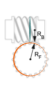
Gear Geometry
The rack-and-pinion constraint is parameterized in terms of the dimensions of the
worm and gear pitch circles. The pitch circles are imaginary circles concentric with
the worm and gear bodies and tangent to the thread contact point. The pitch radii,
labeled RB and
RF in the figure, are the radii
that the worm and gear would have if they were reduced to friction cylinders in
mutual contact.
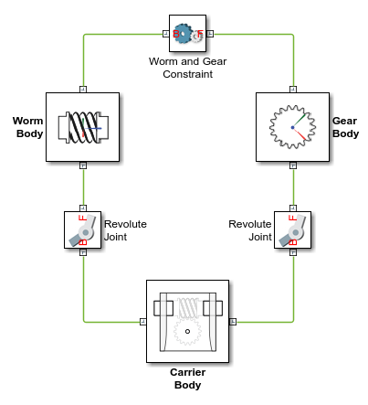
Gear Assembly
Gear constraints occur in closed kinematic loops. The figure shows the closed-loop topology of a simple worm-and-gear model. Joint blocks connect the worm and gear bodies to a common fixture or carrier, defining the maximum degrees of freedom between them. A Worm and Gear Constraint block connects the worm and gear bodies, eliminating one degree of freedom and effectively coupling the worm and gear motions.
Assembly Requirements
The block imposes special restrictions on the relative positions and orientations of the gear connection frames. The restrictions ensure that the gears assemble only at distances and angles suitable for meshing. The block enforces the restrictions during model assembly, when it first attempts to place the gears in mesh, but relies on the remainder of the model to keep the gears in mesh during simulation.
Position Restrictions
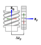
The distance between the base and follower frame z-axes, denoted dB-F in the figure, must be equal to the distance between the gear centers.
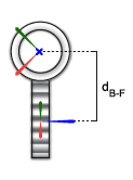
The translational offset between the base and follower frame origins along the follower frame z-axis, denoted ΔZF in the figure, must be zero.
Orientation Restrictions
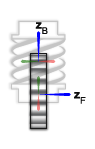
The z-axes of the base and follower frames must be perpendicular to each other. The z-axes are shown in blue in the figure.
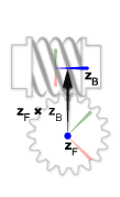
The cross product of the follower frame z-axis with the base frame z-axis must be a vector aimed from the follower frame origin to the base frame z-axis. The z-axes and their cross-product vector are shown in the figure. The cross product is defined as .
Examples

Using the Worm and Gear Constraint Block - Solar Tracker
Illustrates the use of the Worm and Gear Constraint block to model a solar tracker. A slew drive containing a worm and gear constraint powers the yaw rotation of the solar trackers. The worm and gear geometry gives a large reduction in a single stage of gearing which provides precision tracking and high torque output. The yaw rotation is specified as a motion input to the gear revolute joint and the necessary actuator torque is automatically computed at the worm revolute joint.
Ports
Frame
Output
Parameters
Extended Capabilities
Version History
Introduced in R2016b