Lead Screw Joint
Joint with coupled rotational and translational degrees of freedom
Libraries:
Simscape /
Multibody /
Joints
Description
The Lead Screw Joint block represents a joint that has one degree of freedom and models a pair of coupled rotation and translation, as shown in the image.
During simulation, the joint constrains the z-axes of the base and follower frames to be aligned. The follower frame origin can translate along the base z-axis while the follower x-axis and y-axis rotate about the base frame z-axis. The translation is proportional to the rotation based on the value of the Lead and Direction parameters.
To specify the target of the initial state for the joint, use the parameters under State Targets. You can specify the targets based on the relative rotation or translation between the joint frames. To specify the joint mode configuration, use the Mode parameter. For more details, see Mode Configuration under the Ports and Parameters sections.
The joint block has ports that output sensing data, such as position, velocity, acceleration, force, and torque, that you can use to perform analytical tasks on a model.
Examples
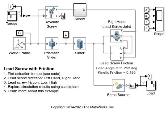
Lead Screw with Friction
Models a lead screw with friction. The constraint force in the lead screw is measured and used to calculate the friction torque within the lead screw. A continuous stick-slip friction model is used to determine the coefficient of friction based on the relative rotational speed of the two parts connected by the lead screw.
Cartesian 3-D Printer
Models a Cartesian 3-D printer. The model allows you to specify the rotational motion of the motor on each axis to define a printing path. In this example, the printing head moves along the edges of two letters, S and M, using the predefined rotational motions.
Using the Lead Screw Joint Block - Linear Actuator
Illustrates the use of the Lead Screw Joint block to model a linear actuator. The Lead Screw Joint block converts rotational motion at the Revolute Joint block to translational motion at the four Cylindrical Joint blocks. The translational motion is specified as a motion input to a cylindrical joint and the necessary actuator torque is automatically computed at the revolute joint.
Ports
Frame
B — Base frame
frame
Base frame of the joint block.
F — Follower frame
frame
Follower frame of the joint block.
Input
mode — Joint mode control
physical signal
Input port that controls the mode of the joint. The signal must be a unitless scalar. The
joint mode is normal when the input signal is 0
, disengaged when
the input signal is -1
, and locked when the input signal is
1
. You can change the mode at any time during the
simulation.
The table shows how the position and velocity of the joint change during transitions between modes.
Transitions | Position | Velocity |
---|---|---|
Normal to Locked | The joint position retains the current value and remains constant after the transition. | The joint velocity becomes zero and remains constant after the transition. |
Normal to Disengaged | The joint position retains the current value but can change in any direction after the transition. | The joint velocity retains the current value but can change in any direction after the transition. |
Locked to Normal | The joint position retains the current value but can change in the directions aligned with the joint degrees of freedom (DOFs) after the transition. | The joint velocity remains at zero but can change in the directions aligned with the joint DOFs after the transition. |
Locked to Disengaged | The joint position retains the current value but can change in any direction after the transition. | The joint velocity remains at zero but can change in any direction after the transition. |
Disengaged to Normal | For the directions aligned with the joint DOFs, the joint positions initially take values calculated by using Newton's method and can change thereafter. In the constrained directions, the joint positions become zero and remain constant after the transition. | For the directions aligned with the joint DOFs, the joint velocities initially take values calculated by using Newton's method and can change thereafter. In the constrained directions, the joint velocities become zero and remain constant after the transition. |
Disengaged to Locked | For the directions aligned with the joint DOFs, the joint positions initially take values calculated by using Newton's method and remain constant after the transition. In the constrained directions, the joint positions become zero and remain constant after the transition. | The joint velocity becomes zero and remains constant after the transition. |
Dependencies
To enable this port, under Mode Configuration, set Mode to Provided by Input
.
Output
q — Joint rotation
physical signal
Physical signal port that outputs the rotation angle of the follower frame with respect to the base frame.
Dependencies
To enable this port, under Sensing > Rotation, select Position.
w — First derivative of joint rotation
physical signal
Physical signal port that outputs the first derivative of the joint rotation.
Dependencies
To enable this port, under Sensing > Rotation, select Velocity.
b — Second derivative of joint rotation
physical signal
Physical signal port that outputs the second derivative of the joint rotation.
Dependencies
To enable this port, under Sensing > Rotation, select Acceleration.
p — Joint translation
physical signal
Physical signal port that outputs the joint translation of the follower frame with respect to the base frame.
Dependencies
To enable this port, under Sensing > Translation, select Position.
v — First derivative of joint translation
physical signal
Physical signal port that outputs the first derivative of the joint translation.
Dependencies
To enable this port, under Sensing > Translation, select Velocity.
a — Second derivative of joint translation
physical signal
Physical signal port that outputs the second derivative of the joint translation.
Dependencies
To enable this port, under Sensing > Translation, select Acceleration.
fc — Constraint force
physical signal
Physical signal port that outputs the constraint force that acts in the joint. The force maintains the translational constraints of the joint. For more information, see Measure Joint Constraint Forces.
Dependencies
To enable this port, under Composite Force/Torque Sensing, select Constraint Force.
tc — Constraint torque
physical signal
Physical signal port that outputs the constraint torque that acts in the joint. The torque maintains the rotational constraints of the joint. For more information, see Force and Torque Sensing.
Dependencies
To enable this port, under Composite Force/Torque Sensing, select Constraint Torque.
ft — Total force
physical signal
Physical signal port that outputs the total force that acts in the joint. The total force is the sum of the forces transmitted from one frame to the other through the joint. For more information, see Force and Torque Sensing.
Dependencies
To enable this port, under Composite Force/Torque Sensing, select Total Force.
tt — Total torque
physical signal
Physical signal port that outputs the total torque that acts in the joint. The total torque is the sum of the torques transmitted from one frame to the other through the joint. For more information, see Force and Torque Sensing.
Dependencies
To enable this port, under Composite Force/Torque Sensing, select Total Torque.
Parameters
To edit block parameters interactively, use the Property Inspector. From the Simulink® Toolstrip, on the Simulation tab, in the Prepare gallery, select Property Inspector.
Z Lead Screw Primitive (LSz)
Direction — Handedness of lead screw joint
Right-Hand
(default) | Left-Hand
Handedness of the lead screw joint, specified as
Right-Hand
or Left-Hand
. A
right-handed joint translates a positive rotation into a positive linear movement,
whereas a left-handed joint translates in a negative linear movement from a positive
rotation.
Lead — Lead of lead screw joint
1 mm/rev
(default) | scalar
Lead of the lead screw joint, specified as a scalar with a unit of length/angle. The lead refers to the distance the follower frame moves along the z-axis of the base frame with one complete turn of the follower frame.
Specify Position Target — Whether to specify position target
off
(default) | on
Select this parameter to enable parameters that specify the position target of the joint primitive.
Priority — Priority level of position target
High (desired)
(default) | Low (approximate)
Priority level of the position target, specified as High
(desired)
or Low (approximate)
.
Dependencies
To enable this parameter, under State Targets, select Specify Position Target.
Based On — Motion type to use to specify position target
Translation
(default) | Rotation
Motion type to use to specify the position target, specified as
Translation
or
Rotation
.
Dependencies
To enable this parameter, under State Targets, select Specify Position Target.
Value — Rotational position target
0 deg
(default) | scalar with a unit of angle
Rotational position target, specified as a scalar with a unit of angle.
Dependencies
To enable this parameter, under State Targets > Specify Position Target > Based On, select Rotation.
Value — Translational position target
0 m
(default) | scalar with a unit of length
Translational position target, specified as a scalar with a unit of length.
Dependencies
To enable this parameter, under State Targets > Specify Position Target > Based On, select Translation.
Specify Velocity Target — Whether to specify velocity target
off
(default) | on
Select this parameter to enable parameters that specify the velocity target of the joint primitive.
Priority — Priority level of velocity target
High (desired)
(default) | Low (approximate)
Priority level of the velocity target, specified as High
(desired)
or Low (approximate)
.
Dependencies
To enable this parameter, under State Targets, select Specify Velocity Target.
Based On — Motion type to use to specify velocity target
Translation
(default) | Rotation
Motion type to use to specify the velocity target, specified as
Translation
or
Rotation
.
Dependencies
To enable this parameter, under State Targets, select Specify Velocity Target.
Value — Angular velocity target
0 deg/s
(default) | scalar with unit of angular velocity
Angular velocity target of the joint primitive, specified as a scalar with a unit of angular velocity.
Dependencies
To enable this parameter, under State Targets > Specify Position Target > Based On, select Rotation.
Value — Linear velocity target
0 m/s
(default) | scalar with unit of linear velocity
Linear velocity target of the joint primitive, specified as a scalar with a unit of linear velocity.
Dependencies
To enable this parameter, under State Targets > Specify Position Target > Based On, select Translation.
Mode Configuration
Mode — Joint mode
Normal
(default) | Locked
| Disengaged
| Provided by Input
Joint mode for the simulation, specified as one of these values:
Mode | Description |
---|---|
Locked | Locked mode constrains all the degrees of freedom (DOFs) for the joint. The locked joint maintains its initial assembly position with zero velocity during the simulation. The joint block can sense forces or torques in accordance with the settings of the Internal Mechanics, Limits, and Actuation parameters. |
Normal | Normal mode enables the DOFs and the constraints of the joint work as intended during the simulation. |
Disengaged | Disengaged mode releases the joint from all constraints throughout the simulation. The settings for Internal Mechanics, Limits, and Actuation parameters do not affect the disengaged joint. All output ports output zero. |
Provided by Input | The Provided by Input option allows you to specify the joint mode
by using an input signal. For more information, see the port
mode in the Input
section. |
Composite Force/Torque Sensing
Direction — Measurement direction
Follower on Base
(default) | Base on Follower
Measurement direction, specified as one of these values:
Follower on Base
— The block senses the force and torque that the follower frame exerts on the base frame.Base on Follower
— The block senses the force and torque that the base frame exerts on the follower frame.
This parameter affects only the output signals under the Composite Force/Torque Sensing section. Reversing the direction changes the sign of the measurements. For more information, see Force and Torque Measurement Direction.
Resolution Frame — Frame used to resolve measurements
Base
(default) | Follower
Frame used to resolve the measurements, specified as one of these values:
Base
— The block resolves the measurements in the coordinates of the base frame.Follower
— The block resolves the measurements in the coordinates of the follower frame.
This parameter affects only the output signals under the Composite Force/Torque Sensing section.
Extended Capabilities
C/C++ Code Generation
Generate C and C++ code using Simulink® Coder™.
Version History
Introduced in R2015a
MATLAB 명령
다음 MATLAB 명령에 해당하는 링크를 클릭했습니다.
명령을 실행하려면 MATLAB 명령 창에 입력하십시오. 웹 브라우저는 MATLAB 명령을 지원하지 않습니다.
Select a Web Site
Choose a web site to get translated content where available and see local events and offers. Based on your location, we recommend that you select: .
You can also select a web site from the following list:
How to Get Best Site Performance
Select the China site (in Chinese or English) for best site performance. Other MathWorks country sites are not optimized for visits from your location.
Americas
- América Latina (Español)
- Canada (English)
- United States (English)
Europe
- Belgium (English)
- Denmark (English)
- Deutschland (Deutsch)
- España (Español)
- Finland (English)
- France (Français)
- Ireland (English)
- Italia (Italiano)
- Luxembourg (English)
- Netherlands (English)
- Norway (English)
- Österreich (Deutsch)
- Portugal (English)
- Sweden (English)
- Switzerland
- United Kingdom (English)