Schedule Editor
View and edit the schedule of model components (partitions)
Description
The Schedule Editor is a scheduling tool that represents the components in the model known as partitions, the data connections between them, and the order of those partitions.
Partitions are the components of the model that execute independently as tasks. The data connections between the partitions show the flow of the data between those partitions. The scheduling of these partitions is based on the rates and the events in the model. This schedule is shown in the Order table in the Schedule Editor.
Using the Schedule Editor, you can:
Create partitions and specify their order.
Edit and analyze the schedule of the executable partitions without disturbing the structure of the model.
Visualize how Simulink® executes partitions.
Changes made in the Schedule Editor affect both, simulation and code generation.
Using the Schedule Editor
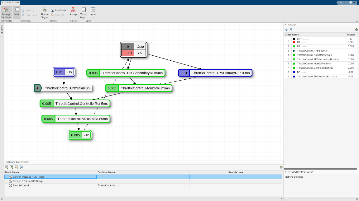
The Schedule Editor consists of two parts representing two different views of partitions in the model:
A graph that shows the partitions and the data connections between them.

A table that shows the order in which the partitions execute.

Changing one of the views impacts the other.
To use the Schedule Editor, select Schedule Editor in the
Design section of the Modeling tab. If the
model is already partitioned, you can open the Schedule Editor by clicking the ![]() badge, which appears above the blocks. To see the default
partitions present in the model in the Schedule Editor, update the diagram by clicking the
badge, which appears above the blocks. To see the default
partitions present in the model in the Schedule Editor, update the diagram by clicking the ![]() icon on the toolstrip or by selecting
Ctrl+D. As you create partitions in the model and update
the diagram, partitions appear in the Schedule Editor.
icon on the toolstrip or by selecting
Ctrl+D. As you create partitions in the model and update
the diagram, partitions appear in the Schedule Editor.
To check how the partitions map to the model, right-click the partitions and select Show Source. The Simulink model window appears with every block corresponding to the partition highlighted.
Order
The Order shows the order in which the partitions execute. To change the order, you can drag and drop the partitions. You can also use the Up and Down arrows on the toolstrip. Partitions are sorted based on their rates. You can only reorder the partitions with the same rate. Clicking a partition in the Order, highlights the corresponding partition in the graph. On changing the order, the connections that are affected by this specified change get highlighted.

Connections
Connections between the partitions show data dependencies. You can right-click the connections between the partitions to change the constraints on data connections. The different types of connections illustrate how the partitions behave with each other.
The types of connections are:
Dependency — Indicates that the source always runs before the destination. The dependency connection is a solid line.

Delay — Indicates that the destination runs before the source. When the destination runs before the source, a scheduling delay is introduced. The delay connection is a dashed line.

You can put these types of constraints on connections:
Allow Delay — Inserts a delay when required. When you specify this constraint for a connection, Simulink inserts a delay for that connection only when necessary. The unlock icon on the connections signifies an allowed delay. When you select this constraint on a connection, Simulink prefers these connections to be turned into a delay if necessary over other connections.
This constraint is displayed as one of these options.


Prevent Delay — Prevents delay from being inserted in the connection. When you specify this constraint for a connection, Simulink ensures that the connection is a dependency. The lock icon on the connection indicates that the connection is locked as a dependency and is not changed to a delay.

Events
The Events panel allows you to manage events in the Schedule
Editor. The events in the Schedule Editor can bind with aperiodic partitions to schedule
their execution. You can create events in the Schedule Editor and use these events to send
from Stateflow® to schedule execution of an aperiodic partition. To send the events from the
Stateflow chart, use the send(eventName) command.
In the Events panel, you can see the listeners and the broadcasters
of the event. The icon ![]() denotes the listeners, and the icon
denotes the listeners, and the icon ![]() denotes the broadcasters. When you bind the aperiodic
partition with an event, the aperiodic partition executes when that event is sent. The
broadcaster of the event shows you the path of the Stateflow chart that sends the event.
denotes the broadcasters. When you bind the aperiodic
partition with an event, the aperiodic partition executes when that event is sent. The
broadcaster of the event shows you the path of the Stateflow chart that sends the event.
Click the icon ![]() to create an event in the Schedule Editor, and select a
listener partition from the drop down. You can also bind an event by dragging and dropping
the event over a valid aperiodic partition. When an event is bound to a partition, the event
name appears on the left side of the partition and in, the Trigger
column of the Order table.
to create an event in the Schedule Editor, and select a
listener partition from the drop down. You can also bind an event by dragging and dropping
the event over a valid aperiodic partition. When an event is bound to a partition, the event
name appears on the left side of the partition and in, the Trigger
column of the Order table.
Open the Schedule Editor
Simulink: In the Modeling tab, expand the Design section and select Schedule Editor from System Design.
Simulink model: Click the badge on the partitioned blocks.
Examples
Parameters
More About
From the Events panel, you can manage events in the Schedule
Editor. In the Events panel, you can see the listeners and the
broadcasters of the event. The icon ![]() denotes the listeners, and the icon
denotes the listeners, and the icon ![]() denotes the broadcasters.
denotes the broadcasters.
Version History
Introduced in R2019a