PWM
입력 듀티 사이클에 대응되는 이상적인 펄스 폭 변조 신호 생성

라이브러리:
Simulink /
Discontinuities
설명
PWM 블록을 사용하여 이상적인 펄스 폭 변조 신호를 생성합니다.
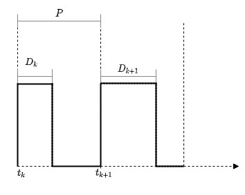
펄스 폭 변조(PWM)는 구형파를 사용하여 아날로그 신호를 인코딩하는 기법입니다. 이 인코딩은 구형파의 한 주기에서 높은 상태로 설정된 비율을 제어하여 이루어집니다. 이 비율이 PWM 신호의 듀티 사이클입니다. 변조 신호와 입력 듀티 사이클 간의 관계는 간단히 다음과 같이 설명될 수 있습니다.
여기서 ymax와 ymin은 각각 출력 신호의 상한과 하한입니다. PWM 블록의 경우 듀티 사이클은 [0,1]로 제한됩니다. 이상적인 PWM 신호는 듀티 사이클 D에 비례합니다.
예제
이 예제에서는 Simulink®에서 PWM 블록을 사용하여 부스트 컨버터를 제어하는 방법을 보여줍니다. 이 모델의 부스트 컨버터는 Simscape™ Electrical™ 라이브러리에 있는 Boost Converter (Simscape Electrical) 블록을 사용합니다.

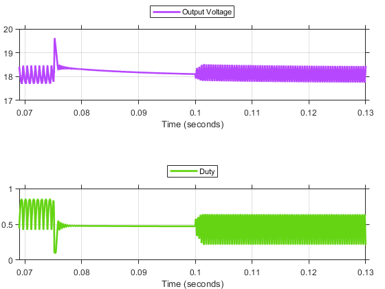
PWM 신호는 부스트 컨버터의 스위칭 소자(게이트)를 제어하는 데 사용됩니다. PID 제어기는 원하는 승압 전압(Vref) 18V를 추종하기 위해 명령 신호(듀티 사이클)를 생성합니다.
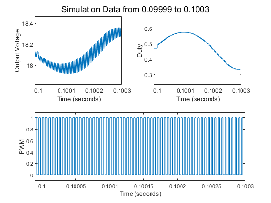
이는 비교적 높은 주파수를 응용한 사례로, 스위칭 게이트가 약 200kHz에서 작동합니다. 따라서 PWM 신호의 펄스 주기는 1/200,000(5e-6초)로 선택됩니다.
작은 시간 스텝을 고려하여, 예제와 함께 제공된 boostconverter_pwm 모델은 0.069초에서의 정상 상태로 로드됩니다.

0.1초 눈금 부근에서 부스트 컨버터 동작의 시각화는 다음과 같습니다.

PWM 제어의 다른 물리 모델링 구현은 펄스 폭 변조 (Simscape Electrical) 항목을 참조하십시오.
포트
입력
펄스 P의 목표 듀티 사이클로, 범위 [0,1] 내의 스칼라로 정의됩니다.
데이터형: double
출력
입력 듀티 사이클에 대응되는 PWM 신호입니다.
데이터형: double
파라미터
출력 신호의 연속적인 펄스의 상승 에지 간의 시간입니다. 작은 값은 고주파 펄스를 나타냅니다.
프로그래밍 방식의 사용법
블록 파라미터: Period
|
| 유형: string형 | 문자형 벡터 |
| 값: 실수형 스칼라 |
디폴트 값: '1'
|
생성된 PWM 신호의 초기 지연 또는 위상 지연을 지정합니다(단위: 초).
프로그래밍 방식의 사용법
블록 파라미터: InitialDelay
|
| 유형: string형 | 문자형 벡터 |
| 값: 숫자형 스칼라 |
디폴트 값: 0
|
PWM 블록이 포함된 대수 루프를 차단하려면 이 파라미터를 활성화합니다.
참고
이 파라미터를 활성화하면 신호 값이 0 또는 그 이하가 되어 듀티 사이클 입력에 오류가 발생합니다.
프로그래밍 방식의 사용법
블록 파라미터: DisallowZeroDutyCycle |
| 유형: string형 | 문자형 벡터 |
값: 'on' | 'off'
|
디폴트 값: 'off'
|
블록이 실행되는 시점과 출력 신호에 대한 샘플 시간을 지정합니다.
off— 입력 샘플에 대한 지연이 경과할 때마다 블록이 실행됩니다. 출력 신호는 '보조 스텝에서 고정됨' 샘플 시간을 갖습니다.on— 샘플 시간 파라미터를 사용하여 지정된 고정 레이트로 블록이 실행됩니다. 출력 신호는 샘플 시간 파라미터를 사용하여 지정된 샘플 시간을 갖습니다.
고정 시간 간격으로 실행을 선택한 경우:
지연 신호 값은 샘플 시간 파라미터에 지정한 값보다 커야 합니다.
지정된 샘플 시간의 정수 배수가 아닌 지연 신호 값은 샘플 시간의 가장 가까운 정수 배수로 내림됩니다. 예를 들어 샘플 시간이
0.1이고 지연 신호 값이0.68인 경우 지연은0.6으로 내림됩니다.
프로그래밍 방식의 사용법
블록 파라미터: RunAtFixedTimeIntervals
|
| 유형: string형 | 문자형 벡터 |
값: 'on' | 'off' |
디폴트 값: 'off'
|
블록 실행 레이트 및 출력 신호 샘플 시간입니다. 지연 신호 값은 지정된 샘플 시간보다 커야 합니다.
지연 신호 값이, 지정된 샘플 시간의 정수 배수가 아닌 경우 지연 값은 샘플 시간의 정수 배수인 가장 가까운 값으로 내림됩니다. 예를 들어 샘플 시간이 0.1이고 지연 값이 0.68인 경우 지연은 0.6으로 내림됩니다.
종속성
이 파라미터를 활성화하려면 고정 시간 간격으로 실행을 선택하십시오.
프로그래밍 방식의 사용법
블록 파라미터: SampleTime
|
| 유형: string형 | 문자형 벡터 |
| 값: 숫자형 스칼라 |
디폴트 값: 0.1
|
블록 특성
데이터형 |
|
직접 피드스루 |
|
다차원 신호 |
|
가변 크기 신호 |
|
영점교차 검출 |
|
알고리즘

시간 tk에서 시작하는 펄스는 다음과 같이 정의됩니다.
여기서 pw는 펄스 폭입니다. 주어진 주기 P에서 pw는 듀티 사이클 D에 비례합니다.
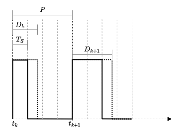
이산 샘플링 모드에서 입력 듀티 사이클 신호는 고정 시간 간격으로 실행 파라미터에 의해 지정된 레이트로 샘플링됩니다.
지정된 샘플링 레이트 tS 에 대해, 펄스 폭 pw에 필요한 샘플 개수는 다음과 같이 표현할 수 있습니다.
여기서 nP는 주기 P의 펄스를 시뮬레이션하는 데 필요한 샘플 개수입니다.

블록의 샘플링 레이트가 tS= 0.25 P로 설정된 주기 P의 공칭 펄스를 고려해 보십시오. 펄스의 한 주기에 필요한 샘플 개수는 nP= 4입니다. 그러므로 입력 듀티 사이클 D= 0.47 의 경우 샘플 개수 n pw는 = 1로 내림됩니다. 이에 따라 해당 주기의 4개 샘플 중 1개에 대해 펄스가 높습니다.
확장 기능
프로덕션 품질 코드에는 권장되지 않습니다. 이는 임베디드 시스템에서 종종 발견되는 리소스 제한과 속도 및 메모리 제한 사항과 관련이 있습니다. 생성된 코드에는 메모리의 동적 할당 및 해제, 재귀, 추가적인 메모리 오버헤드, 매우 가변적인 실행 시간이 포함될 수 있습니다. 이러한 코드는 기능적으로 유효하며 일반적으로 리소스가 풍부한 환경에서는 허용되지만, 더 작은 규모의 임베디드 타깃에서는 지원되지 않을 때가 많습니다.
일반적으로, 연속 블록을 (프로덕션 코드 생성을 지원하는) 상응하는 이산 블록에 매핑하려면 Simulink 모델 이산화를 사용해 보십시오. 모델 이산화를 시작하려면 Simulink® 편집기의 앱 탭에서 앱 아래의 제어 시스템 아래에서 모델 이산화를 클릭하십시오. 단, Second-Order Integrator 블록에 대해서는 모델 이산화가 근사 이산화를 생성하기 때문에 이 블록은 예외입니다.
이 블록에서 HDL 코드 생성 시에는 고정 시간 간격으로 실행 파라미터를 선택해야 합니다.
버전 내역
R2020b에 개발됨
MATLAB Command
You clicked a link that corresponds to this MATLAB command:
Run the command by entering it in the MATLAB Command Window. Web browsers do not support MATLAB commands.
웹사이트 선택
번역된 콘텐츠를 보고 지역별 이벤트와 혜택을 살펴보려면 웹사이트를 선택하십시오. 현재 계신 지역에 따라 다음 웹사이트를 권장합니다:
또한 다음 목록에서 웹사이트를 선택하실 수도 있습니다.
사이트 성능 최적화 방법
최고의 사이트 성능을 위해 중국 사이트(중국어 또는 영어)를 선택하십시오. 현재 계신 지역에서는 다른 국가의 MathWorks 사이트 방문이 최적화되지 않았습니다.
미주
- América Latina (Español)
- Canada (English)
- United States (English)
유럽
- Belgium (English)
- Denmark (English)
- Deutschland (Deutsch)
- España (Español)
- Finland (English)
- France (Français)
- Ireland (English)
- Italia (Italiano)
- Luxembourg (English)
- Netherlands (English)
- Norway (English)
- Österreich (Deutsch)
- Portugal (English)
- Sweden (English)
- Switzerland
- United Kingdom (English)