PEM 전기분해 시스템
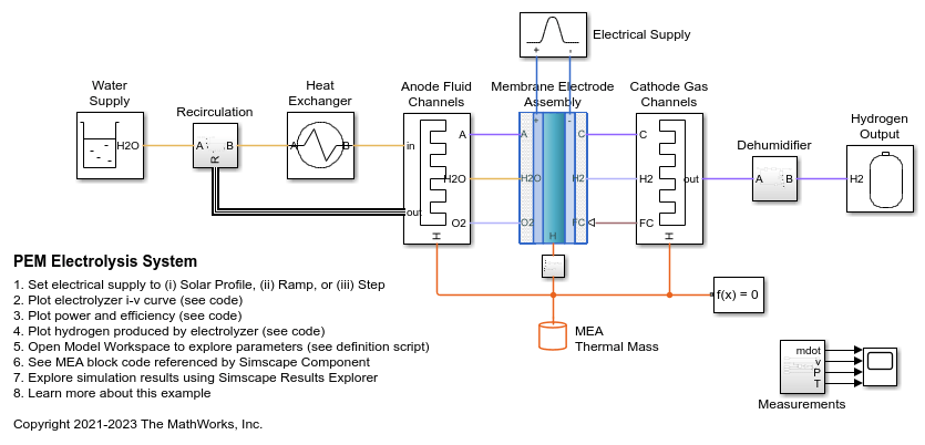
이 예제는 사용자 지정 Simscape™ 블록으로 PEM(양성자 교환막) 물 전해조를 모델링하는 방법을 보여줍니다. PEM 전해조는 전력을 사용하여 물을 수소와 산소로 분리합니다. 이 사용자 지정 블록은 MEA(막전극접합체)를 나타내며, 열 유체 네트워크와 두 개의 습윤 공기 네트워크에 연결됩니다. 여기서 열 유체 네트워크는 물 공급을 모델링하고, 애노드 습윤 공기 네트워크는 산소 흐름을 모델링하며, 캐소드 습윤 공기 네트워크는 수소 흐름을 모델링합니다.
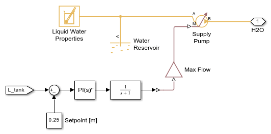
순환 펌프는 전해조의 애노드 측으로 지속적인 물의 흐름을 제공합니다. 사용된 물은 열 유체 네트워크에서 제거되고 과잉수는 재순환됩니다. 애노드에서 생성된 산소는 과잉수 흐름에 의해 운반되며, 애노드 습윤 공기 네트워크에 의해 별도로 모델링됩니다. 분리기 탱크는 산소가 배출되기 전 반환 흐름에서의 물과 산소의 균형을 모델링합니다. 공급 펌프는 시스템에 담수를 보충합니다.
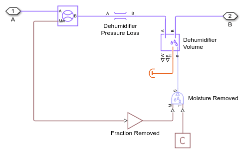
MEA를 가로질러 운반된 모든 물 그리고 캐소드 측에서 생성된 수소는 캐소드 습윤 공기 네트워크에 의해 모델링됩니다. 제습기는 수소에서 원치 않는 수증기를 제거합니다. 압력 조절(레귤레이터) 밸브는 애노드의 대기압과 비교하여 캐소드에서 3MPa의 압력을 유지합니다. MEA 양단 간의 차압으로 인해 전기 삼투압 항력을 상쇄하도록 돕는 유압이 발생하여 물이 운반되며, 캐소드 측에서 물의 양이 감소합니다.
연료전지 스택과 달리 별도의 냉각 네트워크가 필요하지 않습니다. 전해조에 의해 방출된 열은 과잉수에 의해 운반된 다음 열교환기를 통해 환경으로 방출됩니다. 재순환되는 물은 전해조에서 섭씨 80도를 유지하도록 제어됩니다.
이 사용자 지정 MEA 블록은 Simscape 코드 Electrolyzer.ssc에 구현되어 있습니다. 열 유체 포트 H2O는 열 유체 네트워크에서 물을 제거하는 데 사용됩니다. 생성된 H2와 O2 그리고 운반된 H2O는 Controlled Trace Gas Source(MA) 블록과 Controlled Moisture Source(MA) 블록을 사용하여 2개의 습윤 공기 네트워크에 추가됩니다. 과도한 열은 연결된 Thermal Mass 블록으로 열 포트 H를 통해 전달됩니다. 구현에 대한 추가 세부 정보는 코드의 주석을 참조하십시오.
PEM 연료전지 시스템 예제도 참조하십시오.
참고 문헌:
Liso, Vincenzo, et al. "Modelling and experimental analysis of a polymer electrolyte membrane water electrolysis cell at different operating temperatures." Energies 11.12 (2018): 3273.
Mo, Jingke, et al. "Thin liquid/gas diffusion layers for high-efficiency hydrogen production from water splitting." Applied Energy 177 (2016): 817-822.
모델

Anode Fluid Channels 서브시스템

Cathode Gas Channels 서브시스템

Dehumidifier 서브시스템

Electrical Supply 서브시스템

Heat Exchanger 서브시스템

Hydrogen Output 서브시스템

Recirculation 서브시스템

Separator Tank 서브시스템

Water Supply 서브시스템

스코프의 시뮬레이션 결과

Simscape 기록의 시뮬레이션 결과
다음 플롯은 전류-전압(i-v) 곡선과 스택의 셀에서 소비되는 전력을 보여줍니다. 전류가 증가하면 전극 활성화 손실로 인해 초기 전압 상승이 일어나고 이어서 옴 저항으로 인해 전압이 점진적으로 증가합니다. 셀 전압은 전류 밀도 2A/cm^2에서 1.71V입니다.

다음 플롯은 전해조에서 사용되는 전력을 보여줍니다. 다양한 손실로 인해 전력은 수소 생성에 필요한 전력보다 더 큽니다. 차이는 방출된 열입니다.
다음 플롯은 전해조의 열효율도 보여주는데, 열효율은 수소의 발열량을 기준으로 수소를 발생시키는 데 사용되는 전력의 비율을 나타냅니다. 이 전해조는 전류 밀도 2A/cm^2에서 약 87%의 효율을 보입니다.

다음 플롯은 수소가 생성되는 속도, 애노드에서 물이 사용되는 속도를 보여주는 것은 물론 확산, 전기 삼투압 항력, 유압 차이로 인해 캐소드로 물이 운반되는 속도도 보여줍니다. 결과적으로 원하는 순도로 수소를 생성하려면 제습 단계가 필요합니다.
다음 플롯은 생성된 수소의 총 질량과 더 높은 발열량에 기반한 등가 에너지도 보여줍니다. 수소가 연료전지에서 전력을 생성하는 데 사용될 경우 사용 가능한 에너지 양도 나타냅니다.
