Two-Phase Fluid Properties (2P)
Fluid properties for two-phase fluid network

Libraries:
Simscape /
Foundation Library /
Two-Phase Fluid /
Utilities
Description
The Two-Phase Fluid Properties (2P) block sets the
thermophysical properties of a fluid in a two-phase fluid network. These properties, which
include density, viscosity, and specific heat, among others, can extend into the supercritical
region of the fluid (water, by default, with a supercritical region extending up to
100 MPa in pressure).
The properties apply to the whole of the two-phase fluid network (the group of continuously connected two-phase fluid blocks). A network can have only one working fluid, and therefore only one instance of this block. If the network is modeled without this block, the fluid is set to water and its properties are obtained from the domain definition.
The block parameterizes the fluid properties in terms of pressure and normalized internal energy—a linear transformation of the specific internal energy. In a subcooled liquid, the normalized internal energy definition is
where:
is the normalized internal energy of the fluid.
u is the specific internal energy of the fluid.
umin is the lowest specific internal energy allowed in the two-phase fluid network.
uLsat is the specific internal energy of the liquid phase at saturation.
In a superheated vapor, the normalized internal energy definition is
where:
umax is the highest specific internal energy allowed in the two-phase fluid network.
uVsat is the specific internal energy of the vapor phase at saturation.
In a two-phase mixture, the normalized internal energy definition is
These expressions correspond to a normalized internal energy that is at all pressures -1 at the minimum valid specific internal energy, 0 at the liquid saturation boundary, +1 at the vapor saturation boundary, and +2 at the maximum valid specific internal energy.
In a two-phase mixture, the normalized internal energy ranges in value from 0 to 1 and is therefore equivalent to vapor quality—the mass fraction of the vapor phase in a two-phase mixture. In subcooled liquid and superheated vapor, the normalized internal energy behaves as an extension of vapor quality.
The normalized internal energy provides an advantage over the specific internal energy. It transforms the p-u phase diagram so that the subcooled liquid and superheated vapor phases occupy distinct rectangular regions. This transformation, shown in the figure, enables you to specify the fluid properties on separate rectangular p- grids, one for each phase.
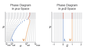
A pressure vector, of length N, and two normalized internal energy vectors, of lengths ML and MV, provide the (p, ) coordinates of the two grids. The pressure vector is common to both grids. The subcooled liquid grid is ML-by-N in size and the superheated vapor grid MV-by-N.
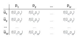
Two-way lookup tables provide the fluid property values on the (p, ) grids. The table rows correspond to different normalized internal energies and the table columns to pressures. Fluid properties in the p- continuum are computed using linear interpolation between the p- data points.
Two-Way Property Lookup Table
Saturated specific internal energy vectors provide the phase boundaries in the (p, ) phase diagram. These separate the different regions of the phase diagram—subcooled liquid, two-phase mixture, and superheated vapor.
Along with the minimum and maximum valid specific internal energy values, the saturated specific internal energy vectors enable the Two-Phase Fluid blocks to convert the normalized internal energies specified in this block into the specific internal energies they use for calculation purposes.
Supercritical Fluids
The fluid can become supercritical. Liquid and vapor then cease to exist as separate phases. Their saturation boundaries merge, forming what is known as the pseudocritical line (in the figure, the segment extending upward from the hump of the p–u phase diagram).
The pseudocritical line divides the fluid into liquid-like and vapor-like regions. As the phases are no longer distinct, however, the transition between the regions is gradual rather than abrupt. This means that at the pseudocritical line, the liquid-like and vapor-like fluids must share the same physical properties.
In this block, the liquid-like portion of the supercritical region is conceived as an extension of the liquid phase. Likewise, the vapor-like portion is conceived as an extension of the vapor phase. In other words, the properties of the supercritical fluid are divided into the liquid and vapor property tables of the block.
The distinction between the phases is, however, superfluous in the supercritical region. For breakpoints over the critical pressure, the liquid and vapor property tables must agree at the saturated boundaries (or, more properly, at the pseudocritical line). The supercritical portions of the tables then behave as a continuous whole.
Consider the kinematic viscosity tables as an example. The bottom row of the
Liquid kinematic viscosity table parameter, as it corresponds to a
normalized specific internal energy of 1, gives the data for the
saturated liquid. The elements in that row corresponding to pressures at or above the
critical point give the data over the pseudocritical line.
Likewise, the upper row of the Vapor kinematic viscosity table
parameter, as it corresponds to a normalized specific internal energy of
1, gives the data for the saturated vapor. The elements in that row
corresponding to pressures at or above the critical point therefore give the data over the
pseudocritical line. To be valid, this data must be exactly the same as that given over
the pseudocritical line in the liquid table.
The pseudocritical line is encoded in the saturation boundaries of the liquid and vapor phases. These are specified in the block via the Saturated liquid specific internal energy vector and Saturated vapor internal energy vector parameters. At pressures below the critical point, the values in one vector will generally differ from those in the other; above the critical point, however, one must always equal the other.
The pseudocritical line can assume any shape. For a simple approximation, it often suffices to extend the specific internal energy of the critical point upward along the pressure axis. This means setting the supercritical portions of the saturated specific internal energy vectors to that critical value. If the exact shape of the pseudocritical line is known, the specific internal energies along that line can be used instead.
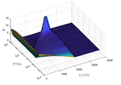
The data for the thermal transport properties—the specific heat, thermal conductivity,
and Prandtl number—often shows a large peak near the critical point. The scale and size of
the peak can, in some cases, cause numerical problems during simulation. To avoid such
problems, the block allows the peak to be clipped. This option is specified in the
Thermal transport properties near critical point block parameter
(by setting it to Clip peak values).
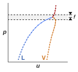
The clipping is limited to a small pressure range around the critical point. That range is specified as a fraction of the critical pressure (f in the figure), and it extends in both directions (by the same amount) from the critical pressure. Within that range, the thermal properties are each limited to a maximum given by the greater of its two end values. The figure shows a plot of the Prandtl number for water with clipping.
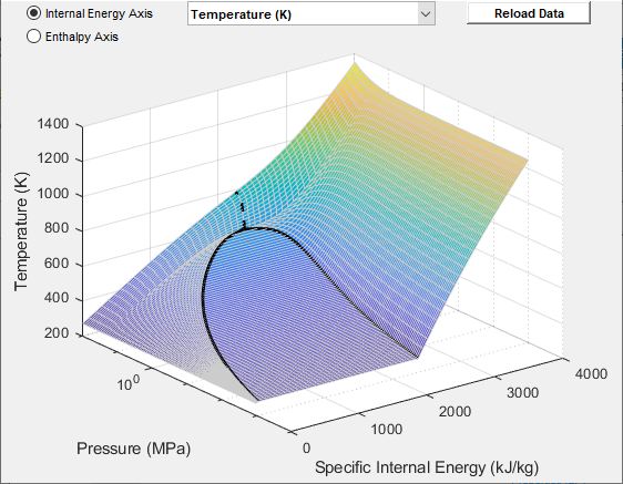
Data Visualization
The block lets you plot the specified two-phase fluid properties as a function of pressure and specific internal energy. Plotting the properties lets you visualize the data before simulating the model.
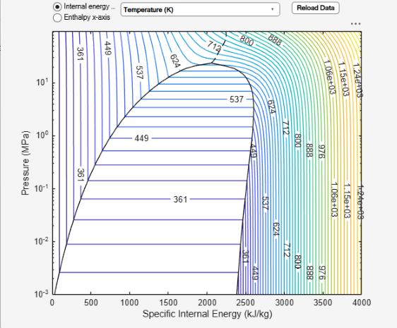
To plot the data, open the block dialog box and, under Plots, click the Plot button next to Two-phase fluid properties (3D) or Two-phase fluid properties (contours). Use the drop-down list located at the top of the plot to select the fluid property to visualize. Click the Reload Data button to regenerate a plot following a block parameter update.
Fluid Properties (3D) Plot
Fluid Properties (Contours) Plot
Examples

Cavitation in Two-Phase Fluid
How two-phase fluid components can be used to simulate cavitation. The model is a translational mechanical converter driven by an oscillating pressure source. During the negative portion of the pressure source cycle, the fluid cavitates, reducing the force produced by the converter. As a result, the converter displacement drifts and does not return to the starting position.
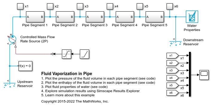
Fluid Vaporization in Pipe
Model the vaporization of water to generate steam. Liquid water enters the pipe at 370 K at a rate of 1 kg/s. The pipe is heated to 1000 K, causing the water flowing inside pipe to saturate.