Multiphase Distributed Parameter Line
R2026bMultiphase Distributed Parameter Line block

To add a block to a model, double-click the canvas and start typing the block name. Then, select the block from the list.
Libraries:
Simscape /
Electrical /
Passive /
Lines
Description
The Multiphase Distributed Parameter Line block models a multiphase (M-phase) transmission line using distributed parameters. An M-phase distributed parameter line is an electrical transmission line with multiple conductors whose electrical characteristics are spread continuously along the line.
This block allows you to model either a balanced or an unbalanced line. To choose which
line to model, set the Line type parameter to either
Balanced lines or General lines.
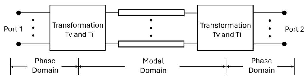
This figure shows the equivalent circuit for an M-phase distributed parameter line in the modal domain.
Balanced M-Phase Lines
For balanced M-phase lines, the resistance, inductance, and capacitance matrices per unit length in the phase domain are
where:
Rs is the self resistance of the transmission line per phase per unit length.
Rm is the line-line mutual resistance per unit length.
Ls is the self inductance of the transmission line per phase per unit length.
Lm is the line-line mutual inductance per unit length.
Cs is the self capacitance of the transmission line per phase per unit length.
Cm is the line-line mutual capacitance per unit length.
To transform these matrices from the phase domain to the modal domain, the block defines a transformation matrix Tv or Ti. This matrix is a canonical orthonormal modal transformation for an M-phase transposed and perfectly symmetric line.
In this matrix, M denotes the number of phases and J is an index from 2 to M that defines the successive orthogonal modal vectors. For example, if M is equal to 5, the transformation matrix is:
By applying the transformation matrix to the resistance, inductance, and capacitance matrices, the block calculates these diagonal matrices in the modal domain:
where:
is the individual zero-sequence resistance.
is the individual positive-sequence resistance.
is the individual zero-sequence inductance.
is the individual positive-sequence inductance.
is the individual zero-sequence capacitance.
is the individual positive-sequence capacitance.
By applying the transformation matrix to the phase voltages Vphase and phase currents Iphase, the block calculates the mode voltages Vmode and mode currents Imode:
As a result, by applying the transformation matrix, the block transforms the original M-phase coupled transmission line in the phase domain into an M-phase decoupled transmission line in the modal domain. Then, the block can solve the equations corresponding to these decoupled transmission lines as single-phase equations.
In the modal domain, the block models the lossless distributed parameter line using its characteristic impedance Zc and delay τ. These equations define the impedance and delay for each mode:
where length is the transmission line length and is the propagation speed.
To introduce losses, you can connect N delay-based losses lines in series through a set of resistors:

where N is an integer greater than or equal to 1 and . For more information about modeling delay-based lines, see Transmission Line.
General M-Phase Lines
For multiphase untransposed lines, the diagonal and off-diagonal elements of the
resistance, inductance, and capacitance matrices per unit length are not necessarily
identical. If they are not identical, then set the Line type parameter
to General lines and individually specify the resistance,
inductance, and capacitance matrices per unit length.
The general lines equations are the same as the balanced lines equations, but the block must derive the transformation matrices Tv and Ti from the eigenvalue and eigenvector theory. For more information, see the Section 4.1.5 of the Electromagnetic transients program (EMTP) theory book [1].
You can specify electrical quantities like the resistance, inductance, and capacitance matrices by using the block parameters or you can use a built-in MATLAB® script to calculate the parameter values. To open the script, click the Open live script button next to Calculate parameters at the top of the block mask. The script shows how to calculate the parameters using electrical properties that manufacturers typically provide for the conductors and geometric data that describes the conductors and transmission tower. Enter numerical values in the edit fields and run the script to calculate the parameters. To apply the parameters to the block, click the Apply Parameters button at the bottom of the script.
Assumptions and Limitations
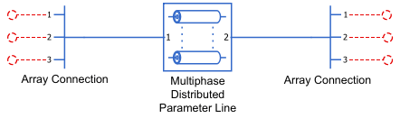
The 1 and 2 ports of this block represent multiple nodes as single ports. The number of nodes inside each port depends on the value of the Number of phases parameter. To access each connection port on both sides of the block, use the Array Connection block.
The Multiphase Distributed Parameter Line block does not support energy accounting. If you try to get energy information for this block using the
getEnergyInfofunction, the function generates an error message.
Ports
Conserving
Parameters
References
[1] Dommel, Hermann W. Electromagnetic Transients Program Manual: (EMTP) Theory Book. Bonneville Power Administration, 1986.
Extended Capabilities
Version History
Introduced in R2026b

