Main Content

Limited-Slip Differential

Reduce velocity difference between two connected shafts

  • Limited-Slip Differential block

Libraries:
Simscape / Driveline / Gears

Description

The Limited-Slip Differential block represents a limited-slip differential (LSD), which is a gear assembly that limits the velocity difference between two connected shafts. The block models the LSD mechanism as a structural component that combines a differential and a clutch.

The differential component in the LSD block is an open differential. An open differential is a gear mechanism that allows two driven shafts to spin at different speeds. In an automobile, a differential allows the inner wheels to spin more slowly than the outer wheels when the vehicle is cornering. A vehicle that has wheel shafts connected by an open differential can get stuck when one of the wheels slips and spins freely due to traction loss. This vehicle stops moving because the driveshaft supplies less power to the wheel with traction than it supplies to the spinning wheel.

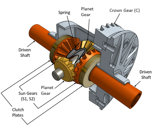
In the same scenario, a vehicle that has an LSD is less likely to get stuck because it contains a clutch assembly that can transmit power to the wheel that retains traction. The clutch component in the LSD block is a friction clutch that has two sets of flat friction plates. The clutch engages when applied pressure exceeds the engagement threshold pressure. In an LSD, a spring preload that separates the sun gears presses the plates in both sets together. When the shafts experience a traction differential, the planet pinion gears exert an additional force in the direction of the high-traction shaft. If the additional pressure exceeds the engagement threshold, the clutch assembly engages. The engagement allows the driveshaft to transmit more power to the slower-spinning high-traction wheel. The additional power reduces the difference in velocity of the two shafts. Because the high-traction wheel continues to rotate, the vehicle continues to move.

The figure shows the orientation of the major components in an LSD mechanism. The driveshaft pinion gear is not visible is this representation.

The Limited-Slip Differential block models the LSD mechanism as a structural component based on the Simscape™ Driveline™ Differential and Disc Friction Clutch blocks. The differential mechanism modeled by the Differential block is a structural component based on two other Simscape Driveline blocks, the Simple Gear and the Sun-Planet Bevel. The block diagram shows the structural components of the LSD.

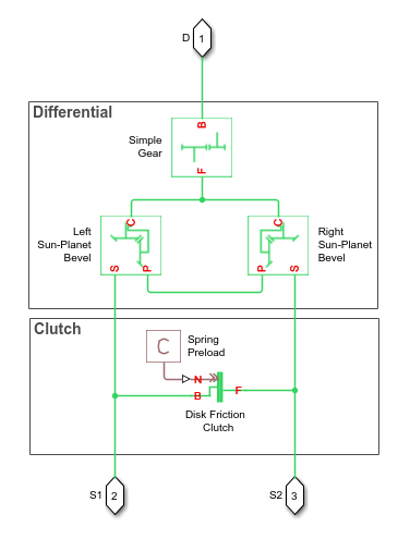
The ports of the Limited-Slip Differential block are associated with the driveshaft (port D) and the two driven shafts (ports S1 and S2), which connect the sun gears to the wheels.

The Limited-Slip Differential block enables you to specify inertias only for the gear carrier and internal planet gears. By default, the inertias of the outer gears are assumed negligible. To model the inertias of the outer gears, connect Simscape Inertia blocks to the D, S1, and S2 ports.

The table shows the rotation direction of the driven shaft ports for different block parameterizations and input conditions.

Rotation Direction of the Driven Shaft Ports (S1 and S2)Crown Gear Location Relative to the CenterlineRotation Direction of Driveshaft Port DRelative Slippage Across the Differential
PositiveRightPositive0
  • Positive for the nonslipping port

  • Negative the slipping port

RightPositive> 0
NegativeRightNegative0
  • Negative for the nonslipping port

  • Positive the slipping port

RightNegative> 0
NegativeLeftPositive0
  • Negative for the nonslipping port

  • Positive the slipping port

LeftPositive> 0
PositiveLeftNegative0
  • Positive for the nonslipping port

  • Negative the slipping port

LeftNegative> 0

Model

To examine the mathematical models for the structural components of the Limited-Slip Differential block, see:

Thermal Model

You can model the effects of heat flow and temperature change by enabling the optional thermal port. To enable the port, set Friction model to Temperature-dependent efficiency.

Ports

Conserving

expand all

Rotational mechanical conserving port associated with the driveshaft.

Rotational mechanical conserving port associated with the sun gear 1 shaft.

Rotational mechanical conserving port associated with the sun gear 2 shaft.

Thermal conserving port associated with heat flow.

Dependencies

To enable this port, in the Differential tab, set Friction model to Temperature-dependent efficiency.

Parameters

expand all

Differential

Location of the bevel crown gear relative to the centerline of the gear assembly.

Fixed ratio, gD, of the number of crown gear teeth NC to the number of driveshaft pinion gear teeth ND. This gear ratio must be strictly greater than 0. The crown gear is rigidly mounted to the carrier.

Friction model for the block:

  • No meshing losses - Suitable for HIL simulation— Gear meshing is ideal.

  • Constant efficiency— Transfer of torque between the gear wheel pairs is reduced by a constant efficiency, η, such that 0<η1.

  • Temperature-dependent efficiency— Transfer of torque between the gear wheel pairs is defined by the temperature lookup table

Vector of torque transfer efficiencies, [ηSS, ηCD]. Here,

  • ηSS is the output-to-input power ratio that describes the power flow from the driving sun gear to the driven sun gear.

  • ηCD is the output-to-input power ratio that describes the power flow from the crown gear to the driveshaft pinion gear.

The carrier is rigidly mounted to the crown gear. The vector elements must be in the range (0,1].

Dependencies

To enable this parameter, set Friction model to Constant efficiency.

Vector of temperatures used to construct a 1-D temperature-efficiency lookup table. The vector elements must increase from left to right.

Dependencies

To enable this parameter, set Friction model to Temperature-dependent efficiency.

Vector of output-to-input power ratios that describe the power flow from the driving sun gear to the driven sun gear, ηSS. The block uses the values to construct a 1-D temperature-efficiency lookup table.

Each element is an efficiency that relates to a temperature in the Temperature vector. The length of the vector must be equal to the length of the Temperature vector. Each element in the vector must be in the range (0,1].

Dependencies

To enable this parameter, set Friction model to Temperature-dependent efficiency.

Vector of output-to-input power ratios that describe the power flow from the crown gear to the driveshaft pinion gear, ηCD. The block uses the values to construct a 1-D temperature-efficiency lookup table. The carrier gear is rigidly mounted to the crown gear.

Each element is an efficiency that relates to a temperature in the Temperature vector. The length of the vector must be equal to the length of the Temperature vector. Each element in the vector must be in the range (0,1].

Dependencies

To enable this parameter, set Friction model to Temperature-dependent efficiency.

Vector of power thresholds, pth, for sun-carrier and longitudinal driveshaft-casing [pS, pD], respectively. The full efficiency loss applies above these values. Below these values, a hyperbolic tangent function smooths the efficiency factor.

When you set Friction model to Constant efficiency, the block lowers the efficiency losses to zero when no power is transmitted. When you set Friction model to Temperature-dependent efficiency, the block smooths the efficiency factors between zero when at rest and the values provided by the temperature-efficiency lookup tables at the power thresholds.

Dependencies

To enable this parameter, set Friction model to Constant efficiency or Temperature-dependent efficiency.

Vector of viscous friction coefficients [μS, μD] for the sun-carrier and longitudinal driveshaft-casing gear motions, respectively.

Inertia model for the block:

  • Off — Model gear inertia.

  • On — Neglect gear inertia.

Moment of inertia of the planet gear carrier assembly including the crown gear. This value must be positive.

Dependencies

To enable this parameter, set Inertia to On.

Moment of inertia of the combined planet gears. This value must be positive.

Dependencies

To enable this parameter, set Inertia to On.

Clutch

Number, N, of friction-generating contact surfaces inside the clutch.

Effective moment arm radius, reff, that determines the kinetic friction torque inside the clutch.

Force that the spring preload exerts on the clutch plate assemblies. Must be greater than or equal to zero.

Static or peak value of the friction coefficient. The static friction coefficient must be greater than the kinetic friction coefficient.

Dependencies

To enable this parameter, set Friction model to No meshing losses - Suitable for HIL simulation or Fixed kinetic friction coefficient.

Vector of static or peak values of the friction coefficient for a given temperature. The vector must be the same length as the Temperature. Each element must be greater than the maximum value of the corresponding row in the Kinetic friction coefficient matrix.

Dependencies

To enable this parameter, set Friction model to Temperature-dependent efficiency.

Vector of input values for the relative velocity. The values in the vector must increase from left to right. The minimum number of values depends on the interpolation method that you select. For linear interpolation, provide at least two values per dimension. For smooth interpolation, provide at least three values per dimension.

Vector of output values for the kinetic friction coefficient. All values must be greater than zero.

Dependencies

To enable this parameter, in the Differential tab, set Friction model to No meshing losses - Suitable for HIL simulation or Constant efficiency.

Matrix of output values for the kinetic friction coefficient. All values must be greater than zero.

Dependencies

To enable this parameter, in the Differential tab, set Friction model to Temperature-dependent efficiency.

Interpolation methods for approximating the output value when the input value is between two consecutive grid points. To optimize performance, select Linear. To produce a continuous curve with continuous first-order derivatives, select Smooth.

For more information on interpolation algorithms, see PS Lookup Table (1D).

Extrapolation methods for approximating the output value when the input value is outside the range specified in the argument list. To produce a curve with continuous first-order derivatives in the extrapolation region and at the boundary with the interpolation region, select Linear. To produce an extrapolation that does not go above the highest point in the data or below the lowest point in the data, select Nearest.

For more information on interpolation algorithms, see PS Lookup Table (1D).

Maximum slip velocity at which the clutch can lock. The slip velocity is the signed difference between the base and follower shaft angular velocities, w=wFwB. When the kinetic friction torque is nonzero and the transferred torque is within the static friction torque limits, the clutch locks if the actual slip velocity falls below the velocity tolerance.

Clutch state at the start of simulation. The clutch can be in one of two states, locked and unlocked. A locked clutch constrains the base and follower shafts to spin at the same velocity, that is, as a single unit. An unlocked clutch allows the two shafts to spin at different velocities, resulting in slip between the clutch plates.

Thermal Port

To enable these settings, set Friction model to Temperature-dependent efficiency.

Thermal energy required to change the component temperature by a single temperature unit. The greater the thermal mass, the more resistant the component is to temperature change.

Dependencies

To enable this parameter, setFriction model to Temperature-dependent efficiency.

Block temperature at the start of simulation. The initial temperature sets the initial component efficiencies according to their respective efficiency vectors.

Dependencies

To enable this parameter, set Friction model to Temperature-dependent efficiency.

More About

expand all

Extended Capabilities

C/C++ Code Generation
Generate C and C++ code using Simulink® Coder™.

Version History

Introduced in R2017a