Async Interrupt
Generate Versa Module Eurocard (VME) interrupt service routines (ISRs) that execute downstream subsystems or Task Sync blocks
Libraries:
Simulink Coder /
Asynchronous /
Interrupt Templates
Description
For each specified VME interrupt level in the example RTOS (VxWorks®), the Async Interrupt block generates an interrupt service routine (ISR) that calls one of the following:
A function call subsystem
A Task Sync block
A Stateflow® chart configured for a function call input event
Note
Use the blocks in the Interrupt Templates block library (Async Interrupt and Task Sync) for simulation and code generation. These blocks provide starting point examples to help you develop custom blocks for a target environment.
Assumptions and Limitations
The block supports VME interrupts 1 through 7.
The block uses these RTOS (VxWorks) system calls:
sysIntEnablesysIntDisableintConnectintLockintUnlocktickGet
Performance Considerations
Execution of large subsystems at interrupt level can have a significant impact on interrupt response time for interrupts of equal and lower priority in the system. Usually, it is best to keep ISRs as short as possible. Connect only function-call subsystems that contain a few blocks to an Async Interrupt block.
A better solution for large subsystems is using the Task Sync block to
synchronize the execution of the function-call subsystem to an RTOS task. Place the Task
Sync block between the Async Interrupt block and the function-call
subsystem. The Async Interrupt block then uses the Task Sync block
as the ISR. The ISR releases a synchronization semaphore (performs a
semGive) to the task, and returns immediately from interrupt level. The
example RTOS (VxWorks) then schedules and runs the task. See the description of the Task
Sync block.
Examples
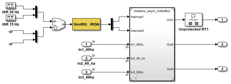
Pass Asynchronous Events in RTOS as Input to a Referenced Model
Generate code for a model that triggers asynchronous events that get passed as input to a referenced model.
Ports
Input
Output
Parameters
Version History
Introduced in R2006a