Design and Generate ros2_control Trajectory Controller for UR5e
Manipulator Using Simulink
3-D trajectory control enables robotic manipulators to perform intricate operations such as assembly of delicate parts, coating irregular surfaces, welding complex structures, or handling hazardous materials, with a high degree of accuracy and repeatability. Some of the challenges in designing a successful 3-D trajectory controller are:
Ability to iteratively test the robustness and stability of the controller
Ensuring real-time performance
Dynamic parameter tuning
This topic shows how you can use Simulink® to design, validate and generate code for a 3-D trajectory controller for UR5e robotic manipulator.
Design, Test and Validate 3-D Trajectory Controller in Simulink
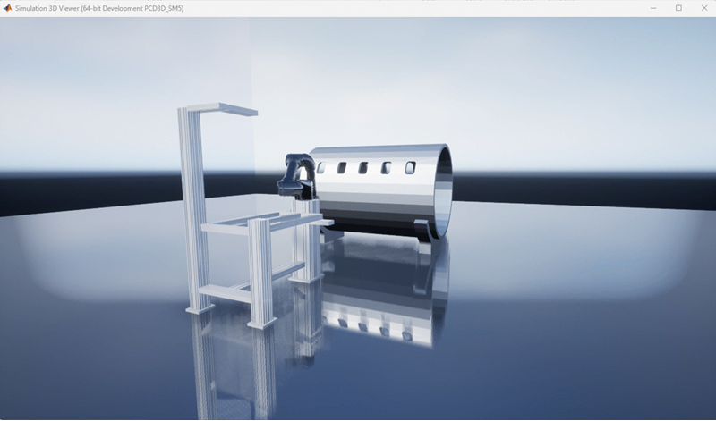
To design and iteratively test the 3-D trajectory controller, you first use co-simulation between Simulink and Unreal Engine®. You can create a photo-realistic scene with the manipulator and any other objects using Unreal Engine and design the controller in a Simulink model for testing and validation.
Generate C++ Code for Controller and Deploy as ros2_control Plugin
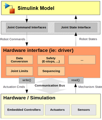
After you validate the controller, you can use configure the controller Simulink model with ROS 2 Control interfaces, auto-generate C++ code, package it
and deploy the controller as a ros2_control plugin. The ros2_control framework provides a flexible and extensible architecture to
design 3-D trajectory controllers for robotic manipulators. It also supports real-time
performance, lifecycle management, and offers robust tools for testing and dynamic
parameter tuning. The data flow between the controller and Simulink is shown in this diagram:
Examples
These examples detail the steps involved in designing, testing and generating code for the 3-D trajectory controller: