dca1000
R2026bConnect to TI mmWave radar sensor and DCA1000EVM to capture raw ADC data for live processing or offline processing
Since R2024b
Description
The
dca1000
System object™ connects to a Texas Instruments® (TI) DCA1000EVM capture card that allows you to receive ADC Data (IQ Data )
from TI mmWave radar. You can use the object to read ADC data for real-time processing or
record the ADC data for processing at a later time.
The following image shows a simple connection diagram between host PC, DCA1000EVM and TI mmWave radar.

The Hardware Setup window in the support package guides you to make the hardware
connection and complete the other required setup. To run Hardware Setup, execute mmWaveRadarSetup
(this is a one time setup). After the hardware setup, to receive ADC (IQ) data from the TI
mmWave radar:
Create the
dca1000object and set its properties.To read one radar data cube for real time processing, call the object as if it were a function.
To record ADC data to a file in a host PC, call the
startRecordingfunction of the object.
Creation
Description
connects to a TI mmWave radar sensor specified by iqDataSource = dca1000(boardname)boardname and
DCA1000EVM capture card. The TI mmWave radar sensor and DCA1000EVM capture card are
connected to the host computer's serial port and Ethernet port, respectively. The
iqDataSource connection object has default property values. When
you use this syntax, MATLAB® automatically detects the serial port at which the TI mmWave radar
sensor is connected. Use this syntax when only one TI mmWave radar sensor is
connected to the host computer.
sets Properties using one or more
name-value arguments. iqDataSource = dca1000(boardname,Name=Value)
For example, iqDataSource = dca1000("IWR6843ISK",ConfigFile=
"C:\Users\User1\PrototypeV3\configMaxRangResolution.cfg") connects to
the DCA1000EVM that is connected to a IWR6843ISK radar board (with both boards
connected to your host computer), and prepares for reading raw ADC data by using the
configuration specified in the file configMaxRangResolution.cfg in
the specified path.
Input Arguments
Name-Value Arguments
Properties
Usage
Description
reads
one radar data cube for live processing of raw ADC (IQ) data from the TI mmWave
radar sensor using DCA1000EVM. If you are using a configuration corresponding to
advanced frame configuration, each call returns IQ data for one subframe, cycling
through the subframes frame-by-frame. iqData = iqDataSource()
System objects may be called directly like a function instead of using the step method. For example, y = step(obj) and y = obj() are equivalent.
[
reads one radar data cube corresponding to a single subframe and returns the
subframe number. If you are using a configuration corresponding to advanced frame
configuration, each call returns IQ data for one subframe along with its subframe
number, cycling through the subframes frame by frame. For example, if the
configuration contains four subframes, the first call returns the data cube for
subframe 1, the second call returns the data cube for subframe 2, and so on, with
the sequence continuing cyclically.iqData,subFrameNum] = iqDataSource()
For example, consider a dca1000 object created with config
file corresponding to advanced frame config with 4
subframe:
dcaObj = dca1000('IWR6843AOPEVM',ConfigFile = 'xwr68xx_AOP_advanced.cfg')
The corresponding output looks like this:
[iqData1,subFrameNum1] = dcaObj();  % data cube corresponding to first subframe, subFrameNum1 = 1
[iqData2,subFrameNum2] = dcaObj();  % data cube corresponding to second subframe, subFrameNum2 = 2
[iqData3,subFrameNum3] = dcaObj();  % data cube corresponding to third subframe, subFrameNum3 = 3
[iqData4,subFrameNum4] = dcaObj();  % data cube corresponding to 4=fourth subframe subframNum4 = 4
Output Arguments
Object Functions
To use an object function, specify the
System object™ as the first input argument. For
example, to release system resources of a System object named obj, use
this syntax:
release(obj)
Examples
Read ADC radar data cube from TI mmWave Radar using DCA1000EVM
Connect to a DCA1000EVM, which is connected to a TI IWR6843ISK mmWave radar. If you
are using the function for the first time, make sure to run hardware setup process
(execute mmWaveRadarSetup command and follow the steps displayed in
the screens). Ensure that you have completed the required hardware connections and that
the network connection associated with DCA1000EVM is configured with the static IP
192.168.33.30. The detailed steps for this are also explained in
the Hardware Setup process.
Create a dca1000 object specifying the TI mmWave radar board
name.
boardName = "IWR6843ISK";
iqDataSource = dca1000(boardName)
iqDataSource =

  dca1000 with properties:

              BoardName: "IWR6843ISK"
             ConfigPort: "COM6"
          HostIPAddress: "192.168.33.30"
         UDPPacketDelay: 25 (us)
             ConfigFile: "C:\ProgramData\MATLAB\SupportPackages\R2024bPrerelease\toolbox\
target\supportpackages\timmwaveradar\configfiles\xwr68xx-IQDataStreaming.cfg"

Recording Properties
       RecordLocation: "C:\ProgramData\MATLAB\dca1000Data"
     RecordFilePrefix: "iqData"
       RecordDuration: 10 (s)
          MaxFileSize: 1024 (MB)

Show all properties all functions
Call iqDataSource object to read one sample of IQ radar data cube
from the TI mmWave Radar using DCA1000EVM.
% Read one radar data cube from the TI Radar
% connected with the capture card DCA1000 EVM
radarDataCube = iqDataSource();
radarDataCube is a complex, double-precision, three-dimensional
array of size SamplesPerChirp × NumReceivers ×
NumChirps. However, the AWR2944EVM provides only real-valued ADC
samples. For real-valued signals, the FFT has conjugate symmetry, which means that one
half of the magnitude spectrum is a mirror image of the other half.

Read ADC Radar Cube When Radar is Configured with Advanced Frame Configuration Containing Four Subframes
Create a dca1000 object specifying the TI mmWave radar board name
and an advanced frame configuration file.
dcaObj = dca1000("IWR6843AOPEVM",ConfigFile="xwr68xx_AOP_advanced.cfg")
Tip
You can use a sample advanced frame configuration file provided with the support
package instead of generating a configuration file. The sample files are stored in
the configfiles folder in the mmWaveRadar Support Package install
directory. For more information, see Configure Radar Using a Configuration (.cfg) File for Reading Raw ADC (IQ) Data
Read radar data cube from the TI Radar connected with the capture card DCA1000 EVM.
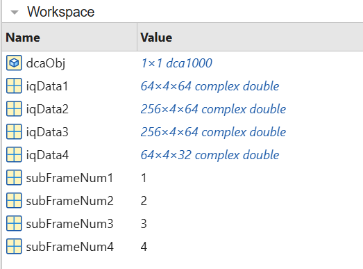
[iqData1,subFrameNum1] = dcaObj();  % data cube corresponding to first subframe, subFrameNum = 1
[iqData2,subFrameNum2] = dcaObj();  % data cube corresponding to second subframe, subFrameNum2 = 2
[iqData3,subFrameNum3] = dcaObj();  % data cube corresponding to third subframe, subFrameNum3 = 3
[iqData4,subFrameNum4] = dcaObj();  % data cube corresponding to 4th subframe subframNum4 = 4
The Workspace gets updated with the new variables and their corresponding values.
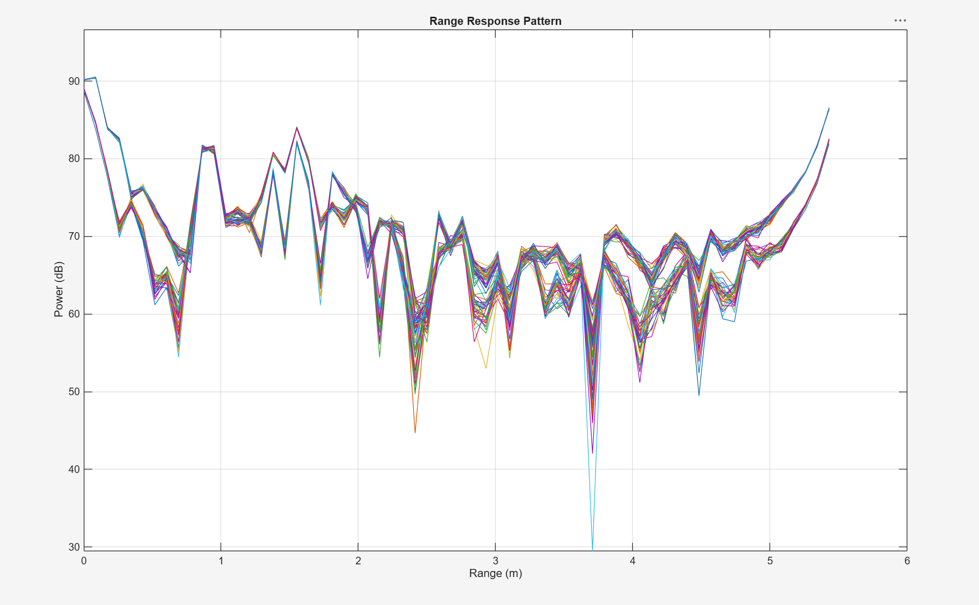
Read and plot specified Subframe Data from TI mmWave Radar Using Advanced Frame Configuration
Connect to a DCA1000EVM connected to a TI IWR6843AOPEVM mmWave radar configured with an advanced frame configuration file containing multiple subframes. Each subframe uses a different chirp profile, enabling simultaneous short-range and long-range operation.
Create a dca1000 object specifying the TI mmWave radar board name
and an advanced frame configuration file.
dcaObj = dca1000("IWR6843AOPEVM",ConfigFile="xwr68xx_AOP_advanced.cfg")
Specify which subframe to process. In this example, use subframe 1 for range response plotting.
% Specify the subframe to plot
reqFrame = 2;
Define the sampling rate and sweep slope for the specified subframe. Because the
dca1000 object properties are 1-by-N vectors when using advanced frame configuration, index into the
property using the subframe number.
% Define a variable to set the sampling rate in Hz for the
% phased.RangeResponse object. Because the dca1000 object provides the
% sampling rate in kHz, convert this rate to Hz.
fs = dcaObj.ADCSampleRate(reqFrame)*1e3;

% Define a variable to set the FMCW sweep slope in Hz/s for the
% phased.RangeResponse object. Because the dca1000 object provides the
% sweep slope in MHz/us, convert this sweep slope to Hz/s.
sweepSlope = dcaObj.SweepSlope(reqFrame) * 1e12;

% Define a variable to set the number of range samples
nr = dcaObj.SamplesPerChirp(reqFrame);
Create a phased.RangeResponse System object for range
filtering.
rangeresp = phased.RangeResponse(RangeMethod="FFT",...
    RangeFFTLengthSource="Property",...
    RangeFFTLength=nr, ...
    SampleRate=fs, ...
    SweepSlope=sweepSlope, ...
    ReferenceRangeCentered=false);
Read ADC data in a loop, processing only the data cubes that correspond to the specified subframe.
% Specify the duration in seconds for which the loop should run
stopTime = 100;
% Start the stopwatch timer
ts = tic;
% Execute the loop until the stopTime specified is reached
while (toc(ts)<stopTime)
    % Capture the ADC data (IQ data) from TI Radar board and DCA1000EVM.
    % Each call returns data for one subframe along with its subframe number.
    [iqData,frameNum] = dcaObj();
    if frameNum == reqFrame
        % Get the data from the first receiver antenna
        iqData = squeeze(iqData(:,1,:));
        % Plot the range response corresponding to the input signal, iqData.
        plotResponse(rangeresp,iqData);
    end
    % Update figures
    drawnow limitrate;
end