Main Content

phased.ADPCACanceller

Adaptive DPCA (ADPCA) pulse canceller

Description

The ADPCACanceller object implements an adaptive displaced phase center array pulse canceller for a uniform linear array (ULA).

To compute the output signal of the space time pulse canceller:

  1. Define and set up your ADPCA pulse canceller. See Construction.

  2. Call step to execute the ADPCA algorithm according to the properties of phased.ADPCACanceller. The behavior of step is specific to each object in the toolbox.

Note

Starting in R2016b, instead of using the step method to perform the operation defined by the System object™, you can call the object with arguments, as if it were a function. For example, y = step(obj,x) and y = obj(x) perform equivalent operations.

Construction

H = phased.ADPCACanceller creates an adaptive displaced phase center array (ADPCA) canceller System object, H. This object performs two-pulse ADPCA processing on the input data.

H = phased.ADPCACanceller(Name,Value) creates an ADPCA object, H, with each specified property Name set to the specified Value. You can specify additional name-value pair arguments in any order as (Name1,Value1,...,NameN,ValueN). See Properties for the list of available property names.

Properties

SensorArray

Uniform linear array

Uniform linear array, specified as a phased.ULA System object.

Default: phased.ULA with default property values

PropagationSpeed

Signal propagation speed

Specify the propagation speed of the signal, in meters per second, as a positive scalar. You can specify this property as single or double precision.

Default: Speed of light

OperatingFrequency

System operating frequency

Specify the operating frequency of the system in hertz as a positive scalar. The default value corresponds to 300 MHz. You can specify this property as single or double precision.

Default: 3e8

PRFSource

Source of pulse repetition frequency

Source of the PRF values for the STAP processor, specified as 'Property' or 'Input port'. When you set this property to 'Property'', the PRF is determined by the value of the PRF property. When you set this property to 'Input port', the PRF is determined by an input argument to the step method at execution time.

Default: 'Property'

PRF

Pulse repetition frequency

Pulse repetition frequency (PRF) of the received signal, specified as a positive scalar. Units are in Hertz. This property can be specified as single or double precision.

Dependencies

To enable this property, set the PRFSource property to 'Property'.

Default: 1

DirectionSource

Source of receiving main lobe direction

Specify whether the targeting direction for the STAP processor comes from the Direction property of this object or from an input argument in step. Values of this property are:

'Property'The Direction property of this object specifies the targeting direction.
'Input port'An input argument in each invocation of step specifies the targeting direction.

Default: 'Property'

Direction

Receiving mainlobe direction (degrees)

Specify the receiving mainlobe direction of the receiving sensor array as a column vector of length 2. The direction is specified in the format of [AzimuthAngle; ElevationAngle] (in degrees). Azimuth angle should be between –180 and 180. Elevation angle should be between –90 and 90. This property applies when you set the DirectionSource property to 'Property'. This property can be specified as single or double precision.

Default: [0; 0]

NumPhaseShifterBits

Number of phase shifter quantization bits

The number of bits used to quantize the phase shift component of beamformer or steering vector weights. Specify the number of bits as a non-negative integer. A value of zero indicates that no quantization is performed. You can specify this property as single or double precision.

Default: 0

DopplerSource

Source of targeting Doppler

Specify whether the targeting Doppler for the STAP processor comes from the Doppler property of this object or from an input argument in step. Values of this property are:

'Property'The Doppler property of this object specifies the Doppler.
'Input port'An input argument in each invocation of step specifies the Doppler.

Default: 'Property'

Doppler

Targeting Doppler frequency (Hz)

Specify the targeting Doppler of the STAP processor as a scalar. This property applies when you set the DopplerSource property to 'Property'. This property can be specified as single or double precision.

Default: 0

WeightsOutputPort

Output processing weights

To obtain the weights used in the STAP processor, set this property to true and use the corresponding output argument when invoking step. If you do not want to obtain the weights, set this property to false.

Default: false

PreDopplerOutput

Output pre-Doppler result

Set this property to true to output the processing result before applying the Doppler filtering. Set this property to false to output the processing result after the Doppler filtering.

Default: false

NumGuardCells

Number of guard cells

Specify the number of guard cells used in the training as an even integer. This property specifies the total number of cells on both sides of the cell under test. This property can be specified as single or double precision.

Default: 2, indicating that there is one guard cell at both the front and back of the cell under test

NumTrainingCells

Number of training cells

Specify the number of training cells used in the training as an even integer. Whenever possible, the training cells are equally divided before and after the cell under test. This property can be specified as single or double precision.

Default: 2, indicating that there is one training cell at both the front and back of the cell under test

Methods

stepPerform ADPCA processing on input data
Common to All System Objects
release

Allow System object property value changes

Examples

collapse all

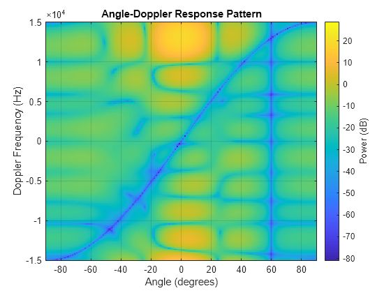
Process a radar data cube using an ADPCA processor. Weights are calculated for the 71st cell of the data cube. Set the look direction to (0,0) degrees and the Doppler shift to 12.980 kHz.

Load radar data file and compute weights

load STAPExampleData;
canceller = phased.ADPCACanceller('SensorArray',STAPEx_HArray,...
    'PRF',STAPEx_PRF,...
    'PropagationSpeed',STAPEx_PropagationSpeed,...
    'OperatingFrequency',STAPEx_OperatingFrequency,...
    'NumTrainingCells',100,...
    'WeightsOutputPort',true,...
    'DirectionSource','Input port',...
    'DopplerSource','Input port');
[y,w] = canceller(STAPEx_ReceivePulse,71,[0; 0],12.980e3);

Create AnglerDoppler System object and plot response

sAngeDop = phased.AngleDopplerResponse(...
    'SensorArray',canceller.SensorArray,...
    'OperatingFrequency',canceller.OperatingFrequency,...
    'PRF',canceller.PRF,...
    'PropagationSpeed',canceller.PropagationSpeed);
plotResponse(sAngeDop,w)

Figure contains an axes object. The axes object with title Angle-Doppler Response Pattern, xlabel Angle (degrees), ylabel Doppler Frequency (Hz) contains an object of type image.

Algorithms

expand all

References

[1] Guerci, J. R. Space-Time Adaptive Processing for Radar. Boston: Artech House, 2003.

[2] Ward, J. “Space-Time Adaptive Processing for Airborne Radar Data Systems,” Technical Report 1015, MIT Lincoln Laboratory, December, 1994.

Extended Capabilities

Version History

Introduced in R2011a