Design and Evaluate Segmented DAC
This example shows how to design and evaluate a segmented DAC using reference architecture and validate the DAC using the DAC Testbench. For this example, use the datasheet of AD9775. This is a commercial, off-the-shelf 14-bit DAC from Analog Devices.
Set Up Segmented DAC Testbench Model
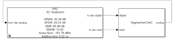
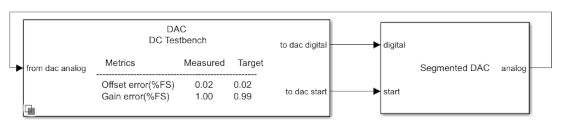
Open the model SegmentedDACTestbench attached to this example as a supporting file. The model consists of a Segmented DAC block and a DAC Testbench.
model = 'SegmentedDacTestbench';
open_system(model);

Segmented DAC Block
The Segmented DAC block is composed of a number of segments, wired in parallel. These segments are each fed by a subset of the input data word. The results of the conversions from each segment DAC are summed to get the output for the full input word.
open_system([model '/Segmented DAC'], 'force');
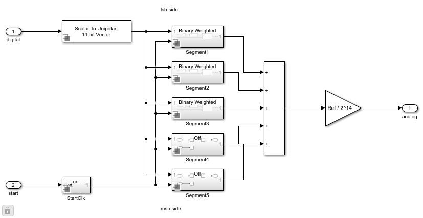
The Logical Vector Conversion block splits the input word into its component bits. Inside each segment a Selector block picks the subset of the input word for that segment and another Logical Vector Conversion block converts it back to a scalar value for the segment DAC to convert. The individual segment DACs are Binary Weighted DAC blocks. Their parameter settings are set during model initialization by the Segmented DAC block. Finally, the segments' outputs are added and scaled to the reference of the Segmented DAC block.
Double click the Segmented DAC block to open the Block Parameters dialog box. Use the table in the center to set parameters of individual segments of the DAC. The effects of the table parameters on the overall operation of the DAC are summarized in the bottom right corner.
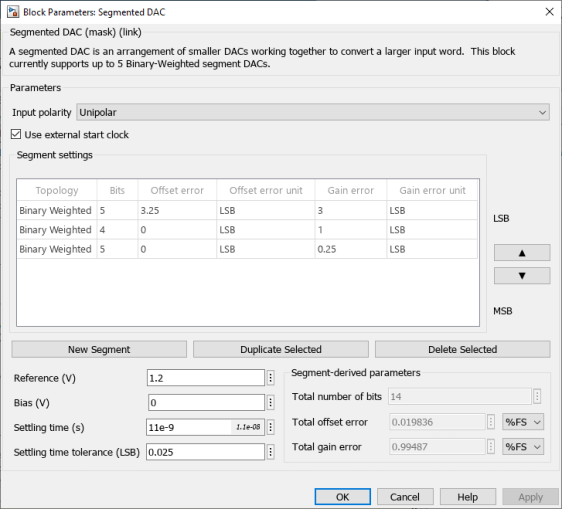
The Input polarity is set Unipolar, the Reference (V) is set to 1.20 V , the Bias (V) is set to 0 V, the Settling time (s) is set to 11e-9 s, and the Settling time tolerance (LSB) is set to 0.025 LSB based on the datasheet.
In the Segment settings table insert a row to have three rows to define a three-segment DAC architecture. Set the Bits of the top and bottom rows to 5 and the Bits of the middle row to 4. This sets the LSB segment (specified by the top row) and the MSB segment (specified by the bottom row) to each be a 5-bit DAC while the middle segment is a 4-bit DAC. Set the Offset error and Gain Error fields for all segments to 0. Click anywhere in a row or Shift+Click on multiple rows in the table to select them. When a row is selected, use the buttons on the right side of the table to move it up or down in the table changing where its segment is in relation to the input word. The top row's segment always converts the LSB and the bottom segment always converts the MSB. Use the buttons below the table to add or remove segments.
Measure DC Performance Metrics Using Endpoint Method
Double click the DAC Testbench block to open the Block Parameters dialog box. The Measurement option is selected as DC. Set the Start conversion frequency (Hz) to 65e6 Hz. In the Setup tab, click the Autofill setup parameters button to automatically propagate the DAC parameters to the testbench. Set the Settling time (s) to 11e-9 s to ensure the DC measurement results are not based on the transitions between codes. In the Target Metric tab, click the Autofill target metric button to automatically propagate the DAC target metrics to the testbench. Apply the changes. Set the Recommended min simulation stop time (s) as model stop time by clicking the Set as model stop time button.
Run the simulation for 5.042 ms.
bdclose(model);
sim(model);
The measured offset and gain errors displayed on the icon of the DAC Testbench are within the Error tolerance (LSB) of their expected values.
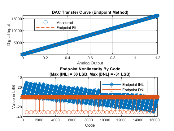
Double click the DAC Testbench block to open the Block Parameters dialog box. Click the Plot DC analysis results button to view the DAC transfer curve, endpoint nonlinearity and best fit nonlinearity.
Measure AC Performance Metrics Using a Single Tone
Double click the DAC Testbench block to open the Block Parameters dialog box. Set the Measurement option as AC. In the Stimulus tab, Start conversion frequency (Hz) is set to 65e6 Hz to allow the DAC's output to settle between conversions. In the Setup tab, click the Autofill setup parameters button to automatically propagate the DAC parameters to the testbench. Apply the changes. Set the Recommended min simulation stop time (s) as model stop time by clicking the Set as model stop time button.
set_param([model '/DAC Testbench'], 'MeasureOption', 'AC');
Open the Segmented DAC block parameters dialog and set the Offset error and Gain error entries in the Segment settings table to 0 for all segments. This prevents the linearity impairments from affecting harmonic performance.
tablestr = "{'1', '5', '0:4', 'Binary Weighted', '0', 'LSB', '0', 'LSB'; " + ...
            "'2', '4', '5:8', 'Binary Weighted', '0', 'LSB', '0', 'LSB'; " + ...
            "'3', '5', '9:13', 'Binary Weighted', '0', 'LSB', '0', 'LSB'}";
set_param([model '/Segmented DAC'], 'SegmentSettings', tablestr);
Run the simulation for 95 us.
set_param(model, 'StopTime', '9.5e-05');
sim(model);
The harmonic distortion measurements are displayed on the icon of the DAC Testbench.