PFD
Phase/frequency detector that compares phase and frequency between two signals
Libraries:
Mixed-Signal Blockset /
PLL /
Building Blocks
Description
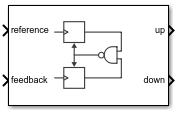
The PFD block produces two output pulses that differ in duty cycle. The difference in the duty cycle is proportional to the phase difference between input signals. In frequency synthesizer circuits, such as phase-locked loops (PLL), the PFD block compares the phase and frequency between the reference signal and signal generated by the VCO block and determines the phase error.
Ports
Input
Input port that transmits reference frequency to determine phase error.
Data Types: double
Output port that transmits the feedback frequency to determine the phase error. In a PLL system, the output of the VCO is fed back through feedback port to PFD after passing through a clock divider.
Data Types: double
Output
Output port that transmits reference frequency to Charge Pump to convert the phase error into current. The difference in the duty cycle of signals in up and down ports is proportional to the phase difference between the signals in reference and feedback ports.
Data Types: double
Output port that transmits feedback frequency to Charge Pump to convert the phase error into current. The difference in the duty cycle of signals in up and down ports is proportional to the phase difference between the signals in reference and feedback ports.
Data Types: double
Parameters
Configuration
Delay added for active output near zero phase offset, specified as a positive real scalar in seconds. Deadband is the phase offset band near zero phase offset for which the PFD output is negligible.
Programmatic Use
Use
get_param(gcb,'DeadbandCompensation')to view the current value of Deadband compensation.Use
set_param(gcb,'DeadbandCompensation',value)to set up Rise/fall time to a specific value.
Data Types: double
Select to enable increased buffer size during simulation. This increases the buffer size of the Variable Pulse Delay, Logic Decision, and Slew Rate blocks inside the PFD block. By default, this option is deselected.
Number of samples of the input buffering available during simulation, specified as a positive integer scalar. This sets the buffer size of the Variable Pulse Delay, Logic Decision, and Slew Rate blocks inside the PFD block.
Selecting different simulation solver or sampling strategies can change the number of input samples needed to produce an accurate output sample. Set the Buffer size to a large enough value so that the input buffer contains all the input samples required.
Dependencies
This parameter is only available when Enable increased buffer size option is selected in the Configuration tab.
Programmatic Use
Use
get_param(gcb,'NBuffer')to view the current value of Buffer size.Use
set_param(gcb,'NBuffer',value)to set Buffer size to a specific value.
Data Types: double
Impairments
Select to add circuit impairments such as rise/fall time and propagation delay to the simulation. By default, this option is selected.
Determine how output step size is calculated:
Select
Defaultto calculate output step size from rise/fall time. Output step size (ΔT) is given by .Select
Advancedto calculate output step size from maximum frequency of interest. Output step size (ΔT) is given by .
Dependencies
To enable this parameter, select Enable Impairments in the Impairments tab.
Maximum frequency of interest at the output, specified as a positive real scalar in Hz.
Dependencies
To enable this parameter, select Enable Impairments in the Impairments tab and choose Advanced for Output step size calculation.
Programmatic Use
Use
get_param(gcb,'MaxFreqInterest')to view the current value of Maximum frequency of interest (Hz).Use
set_param(gcb,'MaxFreqInterest',value)to set Maximum frequency of interest (Hz) to a specific value.
Data Types: double
20% – 80% rise/fall time for the up output port of the PFD, specified as a positive real scalar in seconds.
Dependencies
To enable this parameter, select Enable Impairments in the Impairments tab.
Programmatic Use
Use
get_param(gcb,'RiseFallTime')to view the current value of Rise/fall time (s).Use
set_param(gcb,'RiseFallTime',value)to set Impairments to a specific value.
Data Types: double
Delay from the input port to output port of the PFD, specified as a positive real scalar in seconds.
Dependencies
To enable this parameter, select Enable Impairments in the Impairments tab.
Programmatic Use
Use
get_param(gcb,'PropDelay')to view the current value of Propagation Delay (s).Use
set_param(gcb,'PropDelay',value)to set Propagation Delay (s) to a specific value.
Data Types: double
More About
PFD consists of two synchronous D flip-flops. The reference and feedback signals received at the corresponding ports act as the trigger. The outputs of the two flip-flops pass through a NAND gate, which acts as the reset signal. A pulse delay is introduced after the NAND gate using Variable Pulse Delay block to compensate for deadband.
The impairments are contained in variant subsystems and activated when impairments are enabled. The impairment subsystem utilized Slew Rate block to implement rise/fall time and propagation delay.
References
[1] Banerjee, Dean. PLL Performance, Simulation and Design. Indianapolis, IN: Dog Ear Publishing, 2006.
Version History
Introduced in R2019a
MATLAB Command
You clicked a link that corresponds to this MATLAB command:
Run the command by entering it in the MATLAB Command Window. Web browsers do not support MATLAB commands.
웹사이트 선택
번역된 콘텐츠를 보고 지역별 이벤트와 혜택을 살펴보려면 웹사이트를 선택하십시오. 현재 계신 지역에 따라 다음 웹사이트를 권장합니다:
또한 다음 목록에서 웹사이트를 선택하실 수도 있습니다.
사이트 성능 최적화 방법
최고의 사이트 성능을 위해 중국 사이트(중국어 또는 영어)를 선택하십시오. 현재 계신 지역에서는 다른 국가의 MathWorks 사이트 방문이 최적화되지 않았습니다.
미주
- América Latina (Español)
- Canada (English)
- United States (English)
유럽
- Belgium (English)
- Denmark (English)
- Deutschland (Deutsch)
- España (Español)
- Finland (English)
- France (Français)
- Ireland (English)
- Italia (Italiano)
- Luxembourg (English)
- Netherlands (English)
- Norway (English)
- Österreich (Deutsch)
- Portugal (English)
- Sweden (English)
- Switzerland
- United Kingdom (English)