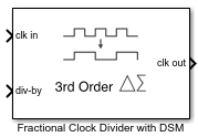
Fractional Clock Divider with DSM
Delta Sigma Modulator based fractional clock divider
Libraries:
Mixed-Signal Blockset /
PLL /
Building Blocks
Description
Using delta sigma (Δ-Σ) modulation technique, a Fractional Clock Divider with DSM reduces the primary fractional spurs by spreading out the range over which the div-by value is varied. This block allows delta sigma modulation of up to 4th order.
Examples
Open the model fractionalClockDivider_w_DSM. The model consists of a Pulse Generator and a Fractional Clock Divider with Accumulator block.
model='fractionalClockDivider_w_DSM';
open_system(model)

The period of the incoming pulse at the clk in port is 4e-7 s. So, the incoming signal has a frequency of 2.5 MHz. The div-by value is set at 2.5. The clock divider uses a second order delta sigma modulator.
Run the simulation for 1e-4 s. The frequency of the output signal is 1.002 MHz.
sim(model);

Ports
Input
Input clock frequency that needs to be divided, specified as a scalar. In a phase-locked loop (PLL) system, the clk in port is connected to the output of a VCO block.
Data Types: double
Ratio of output to input clock frequency, specified as a fractional scalar. The value at the div-by port, N.FF, is split into two parts: the integer part (N) and the fractional part (.FF).
For an nth-order delta sigma modulator, the value at the div-by port is achieved by varying N between 2n different integer values.
Note
For an nth order delta sigma modulator, use a value ≥ 2n at the div-by port.
Data Types: double
Output
Output clock frequency, specified as a scalar. In a PLL system, the clk out port is connected to the feedback input port of a PFD block. The output at the clk out port is a square pulse train of 1 V amplitude.
Data Types: double
Parameters
The order of the delta sigma modulator.
For an nth-order of the delta sigma modulator, the value at the div-by port is achieved by varying the N counter value between 2n different values. Modulator order defines the range of values by which the signal at the clk in port will be divided, providing a division effect similar to N.FF value at the div-by port.
Programmatic Use
Use
get_param(gcb,'dsm')to view the current Delta Sigma Modulator order.Use
set_param(gcb,'dsm',value)to set Delta Sigma Modulator order to a specific value.
Select to enable increased buffer size during simulation. This increases the buffer size of the Logic Decision inside the Fractional Clock Divider with DSM block. By default, this option is deselected.
Number of samples of the input buffering available during simulation, specified as a positive integer scalar. This sets the buffer size of the Logic Decision inside the Fractional Clock Divider with DSM block.
Selecting different simulation solver or sampling strategies can change the number of input samples needed to produce an accurate output sample. Set the Buffer size to a large enough value so that the input buffer contains all the input samples required.
Dependencies
This parameter is only available when Enable increased buffer size option is selected in the Block Parameters dialog box.
Programmatic Use
Use
get_param(gcb,'NBuffer')to view the current value of Buffer size.Use
set_param(gcb,'NBuffer',value)to set Buffer size to a specific value.
More About
The Fractional Clock Divider with DSM subsystem block consists of four delta sigma modulators of orders one to four encapsulated inside the DSM Selector variant subsystem. The output of the DSM selector drives a Single Modulus Prescaler block. Given the Delta Sigma Modulator order, corresponding delta sigma modulator gets activated.
The modulator order defines the range over which the N counter value is varied. For an nth-order delta sigma modulator, N is varied over 2n different values. This variation is achieved by integrating the changes in the fractional part (.FF) from the previous cycle and quantizing the differential changes.
The general form of the transfer function for an nth order delta sigma modulator is:
where
Y(z) = Output of the modulator
X(z) = Input the modulator
E(z) = Quantization error
E(z) is calculated by subtracting the value of input X(z) in the present cycle from its value in the previous cycle. In other words, E(z) is a form of a digital highpass filtering.
The higher-order modulators reduce the primary fractional spurs by alternating N over a larger range of integer values. As a result, the fractional spurs are pushed to higher frequencies in the frequency spectrum and can be filtered more effectively by the loop filter in a PLL system.
For example, if the third-order delta sigma modulator is activated, N is varied over 8 different values, which can range from (N-3) to (N+4).
Delta Sigma Modulator Sequence
| Modulator Order | Range | DSM Sequence |
| 1st | 0, 1 | N, N+1 |
| 2nd | -1, 0, 1, 2 | N-1, N, N+1, N+2 |
| 3rd | -3, -2, -1, 0, 1, 2, 3, 4 | N-3, N-2, …, N+4 |
| 4th | -7, -6, …, 7, 8 | N-7, N-6, …, N+8 |
References
[1] Miller, B. and Conley, R.J., A Multiple Modulator Fractional Divider. IEEE Transactions on Instrumentation and Measurement, vol. 40, no. 3, 1991, pp. 578-583.
Version History
Introduced in R2019a
MATLAB Command
You clicked a link that corresponds to this MATLAB command:
Run the command by entering it in the MATLAB Command Window. Web browsers do not support MATLAB commands.
웹사이트 선택
번역된 콘텐츠를 보고 지역별 이벤트와 혜택을 살펴보려면 웹사이트를 선택하십시오. 현재 계신 지역에 따라 다음 웹사이트를 권장합니다:
또한 다음 목록에서 웹사이트를 선택하실 수도 있습니다.
사이트 성능 최적화 방법
최고의 사이트 성능을 위해 중국 사이트(중국어 또는 영어)를 선택하십시오. 현재 계신 지역에서는 다른 국가의 MathWorks 사이트 방문이 최적화되지 않았습니다.
미주
- América Latina (Español)
- Canada (English)
- United States (English)
유럽
- Belgium (English)
- Denmark (English)
- Deutschland (Deutsch)
- España (Español)
- Finland (English)
- France (Français)
- Ireland (English)
- Italia (Italiano)
- Luxembourg (English)
- Netherlands (English)
- Norway (English)
- Österreich (Deutsch)
- Portugal (English)
- Sweden (English)
- Switzerland
- United Kingdom (English)
