주요 콘텐츠

traceChiefRay

R2026b

Trace chief ray through optical system

Since R2026a

Description

Add-On Required: This feature requires the Optical Design and Simulation Library for Image Processing Toolbox add-on.

chiefRay = traceChiefRay(opsys) traces a chief ray through the optical system opsys. The chief ray is a ray that originates from the field point and passes through the center of the entrance pupil halfway between the upper and lower marginal rays of the optical system.

example

chiefRay = traceChiefRay(opsys,Name=Value) specifies options for tracing a chief ray using one or more name-value arguments. For example, FieldPoints=fieldPoint(Position=[1 0 1]) specifies to trace the chief ray from a light source at the position (1,0,1) in the global reference frame.

Examples

collapse all

Load a wide angle lens from a ZMX file into the workspace.

opsys = zmximport("WideAngleLens.zmx");

Define a field angle representation of a light source at infinity, with a field angle of 20 degrees from the z-axis, using the fieldPoint function.

fp = fieldPoint(Angles=[20 0]);

Trace a chief ray through the optical system using the traceChiefRay object function.

cr = traceChiefRay(opsys,FieldPoints=fp,Wavelengths=587);

Define a hexapolar sampling grid of coordinate points, through which to sample traced rays, using the samplingGrid function.

sg = samplingGrid("Hexapolar",6);

Trace rays through the optical system using the traceRays object function. Specify the defined hexapolar sampling grid using the SamplingGrid name-value argument.

rb = traceRays(opsys,FieldPoints=fp,Wavelength=587,SamplingGrid=sg);

Display the optical system using the view2d object function, and visualize the traced rays through the system using the addRays object function. The chief and sample rays are visualized in blue and red, respectively.

hv = view2d(opsys);
addRays(hv,rb,Color="r")
addRays(hv,cr,Color="b")
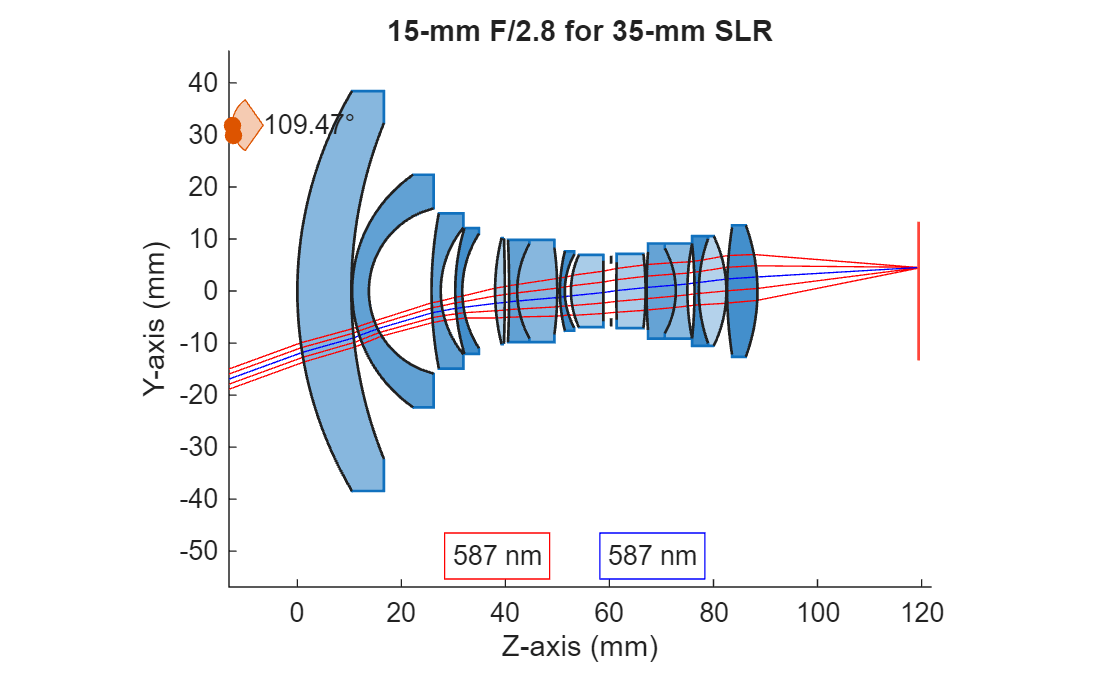
Figure 15-mm F/2.8 for 35-mm SLR contains an object of type optics.ui.opticalsystemviewer2d. The chart of type optics.ui.opticalsystemviewer2d has title 15-mm F/2.8 for 35-mm SLR.

Input Arguments

collapse all

Optical system for which to trace a chief ray, specified as an opticalSystem object.

By default, the traceChiefRay function traces the chief ray from the field points specified by the FieldPoints property of the opticalSystem object, at the operational wavelengths specified by the Wavelengths property of the opticalSystem object.

Name-Value Arguments

collapse all

Specify optional pairs of arguments as Name1=Value1,...,NameN=ValueN, where Name is the argument name and Value is the corresponding value. Name-value arguments must appear after other arguments, but the order of the pairs does not matter.

Example: traceChiefRay(FieldPoints=fieldPoint(Position=[1 0 1])) specifies to trace the chief ray from a light source at the position (1,0,1) in the global reference frame.

Field point representation of a light source, specified as one of these options:

FieldPoints valueLight Source Type

Array of FieldAngle objects

Field points represent light sources that are at an infinite distance from the first surface of the optical system.

Array of FieldPosition objects

Field points represent light sources that are at a finite distance from the first surface of the optical system.
Array of FieldPosition and FieldAngle objectsField points represent two types of light sources, either at an infinite distance and at a finite distance from the first surface of the optical system.

By default, the value of FieldPoints is set by the FieldPoints property of the optical system opsys.

Additional ray properties to compute, specified as one or more of these values.

The traceChiefRay function returns the specified ray properties as additional fields in the RayData property of the RayBundle object in chiefRay. Each value of RayProperties, except "All", creates a field of the same name in RayData.

RayProperties ValueField Value in RayData

"FresnelTerms"

Fresnel reflection and transmission coefficients at each interface, bulk transmission and phase shift, and the total transmittance through the optical system, represented as a structure with these fields.

  • SystemTransmittance — Total transmission through the entire optical system, represented as a NumRays-by-1 vector. Each element of the vector is the total transmission for each ray. NumRays is the number of traced rays.

  • rs — Reflection amplitude coefficient, or complex ratio, for s-polarized incident light, represented as a NumRays-by-MaxRayLength complex-valued matrix.

  • rp — Reflection amplitude coefficient, or complex ratio, for p-polarized incident light, represented as a NumRays-by-MaxRayLength complex-valued matrix.

  • ts — Transmission amplitude coefficient, or complex ratio, for s-polarized incident light, represented as a NumRays-by-MaxRayLength complex-valued matrix.

  • tp — Transmission amplitude coefficient, or complex ratio, for p-polarized incident light, represented as a NumRays-by-MaxRayLength complex-valued matrix.

  • Rs — Reflection power coefficient, which signifies the reflectance, for s-polarized incident light, represented as a NumRays-by-MaxRayLength matrix.

  • Rp — Reflection power coefficient, which signifies the reflectance, for p-polarized incident light, represented as a NumRays-by-MaxRayLength matrix.

  • Ts — Transmission power coefficient, which signifies the transmittance, for s-polarized incident light, represented as a NumRays-by-MaxRayLength matrix.

  • Tp — Transmission power coefficient, which signifies the transmittance, for p-polarized incident light, represented as a NumRays-by-MaxRayLength matrix.

  • BulkTransmission — Transmission coefficient for each ray as it propagates through the bulk medium before reaching the intersected surface, represented as a NumRays-by-MaxRayLength matrix. Each element of the matrix represents the bulk transmission. This value accounts for any absorption or attenuation that occurs along the ray's path before it interacts with a boundary or interface. For example, a value of 1 indicates perfect transmission, or zero loss. Values between 0 and 1 represent partial transmission due to absorption or scattering in the bulk material.

  • BulkPhaseshift — Accumulated phase shift experienced by each ray as it traverses the bulk medium before reaching the intersected surface, represented as a NumRays-by-MaxRayLength matrix. Each element of the matrix represents a bulk phase shift angle, in degrees, due to the optical path length and the refractive index of the medium. This value accounts for any absorption or attenuation that occurs along the ray's path before it interacts with a boundary or interface. For example, a value of 0 means no phase shift occurs, or the ray has not traveled any distance. Positive values indicate accumulated phase due to propagation.

"PolarizationMatrices"

Polarization transformation matrices for each ray and surface intersection, represented as a structure with these fields.

  • BulkMatrix — Polarization change matrix for propagation within each segment as the ray travels through a bulk medium between two surfaces, represented as a NumRays-by-MaxRayLength-by-3-by-3 complex array. For any given index in the first dimension i and second dimension j, BulkMatrix(i,j,:,:) is a 3-by-3 complex matrix that represents the polarization transformation experienced by ray i as it propagates through the medium between surfaces j and j – 1. This matrix describes the effect of the bulk material on the polarization state along each segment of the ray path.

  • SurfaceMatrix — Polarization change matrix at each ray-surface intersection, represented as a NumRays-by-MaxRayLength-by-3-by-3 complex array. For any given index in the first dimension i and second dimension j, SurfaceMatrix(i,j,:,:) is a 3-by-3 complex matrix that represents the polarization transformation experienced by ray i as it propagates through the medium between surfaces j and j – 1. This matrix describes how the polarization state changes due to the reflection, refraction, or transmission at each surface that a ray encounters along its path.

  • SystemMatrix — Overall polarization change matrix for each ray, represented as a NumRays-by-3-by-3 complex array. Each slice SystemMatrix(i,:,:) is a 3-by-3 complex matrix that represents the cumulative polarization change for the ray i.

"All"

Adds all additional ray properties to RayData.

For more information about the global and local coordinate systems, see Coordinate Systems in Optics.

Wavelengths for which to trace rays, specified as an M-element numeric vector. M is the number of wavelengths. Each element of the vector is a wavelength, in nanometers, specified as a positive scalar.

Output Arguments

collapse all

Chief ray traced through the optical system, returned as an N-by-M matrix of RayBundle objects. N is the number of field points, and M is the number of wavelengths for which the chief ray is traced. Each element of the matrix is a RayBundle object that represents the chief ray originating from the corresponding field point.

The chief ray is a ray that originates from the field point and passes through the center of the entrance pupil halfway between the upper and lower marginal rays of the optical system. The intersection of the chief ray with the image plane determines the image position for a particular field point.

Note

The traceChiefRay function attempts to trace rays for each specified field point at the entrance pupil. If rays cannot be traced for a particular field point, the function skips tracing for that field point and continues tracing rays for the remaining field points.

Limitations

The traceChiefRay function determines the chief ray by locating the entrance pupil using marginal ray tracing. For optical systems with surface discontinuities or non-convex apertures, the entrance pupil and corresponding chief ray can be ill-defined. In these cases, traceChiefRay might be unable to identify a unique chief ray for a specific field point and wavelength combination.

To visualize the actual ray paths through such systems, use traceRays and specify an explicit sampling surface using the SamplingSurface argument, such as "first-surface".

Version History

Introduced in R2026a

expand all