Main Content

Thermostatic Expansion Valve (2P)

Flow control valve that maintains evaporator superheat

Since R2020b

  • Thermostatic Expansion Valve (2P) block

Libraries:
Simscape / Fluids / Two-Phase Fluid / Valves & Orifices / Flow Control Valves

Description

The Thermostatic Expansion Valve (2P) block models a valve with a pressure drop that maintains an evaporator superheat in a two-phase fluid network. You typically place this valve between a condenser and an evaporator in a refrigeration system to maintain a specific temperature differential by moderating the flow into the evaporator.

The valve behavior depends on the superheat, which is the difference in temperature between the vapor at the evaporator outlet and the fluid evaporating temperature. The valve opens if the superheat increases to let more flow through, and the valve closes if the superheat decreases to let less flow through. When the superheat drops to or below the value of the Static (minimum) evaporator superheat parameter, then the valve is fully closed. The closed valve reduces the flow through the evaporator, which reduces the heat transfer and increases the outlet temperature. When you use the MOP limit parameter to enable a maximum pressure or temperature limit, the valve closes when the temperature or pressure exceeds the limit.

The bulb sensor at port S measures the evaporator outlet temperature. If you set the Pressure equalization parameter to External pressure equalization, the block uses data from the evaporator at port E for internal pressure equalization. Otherwise, the block uses the pressure at port B for internal pressure equalization. The block balances the bulb pressure, which acts to open the valve, with the valve equalization pressure, which acts to close the valve.

Analytical Parameterization

When you set Valve parameterization to Nominal capacity, superheat, and operating conditions, the block uses an analytical model. In this setting, the block fits the analytical model to the performance data so that when the refrigeration system operates at the specified nominal evaporating temperature, condensing temperature, and condenser subcooling, the block meters enough flow into the evaporator to maintain the evaporator superheat while the block transfers heat at the evaporator capacity. Subcooling is the difference in temperature between the condenser outlet and the condensing temperature.

For this parameterization, the block assumes a straight-charged bulb and assumes that the sensing bulb contains the same fluid as the refrigerant. To model a cross-charged bulb, set Valve parameterization to Tabulated data - quadrant diagram.

Opening Area

The valve operates to control the mass flow rate between a condenser and an evaporator by regulating the effective opening area, Seff. The mass flow rate is

m˙=Seff2vinΔp(Δp2Δplam2)0.25,

where:

  • vin is the inlet specific volume, or the fluid volume per unit mass.

  • Δp is the pressure differential over the valve, pApB.

  • Δplam is the pressure threshold for transitional flow. Below this value, the flow is laminar

    Δplam=pA+pB2(1Blam),

    where Blam is the value of the Laminar flow pressure ratio parameter.

The effective valve area depends on the pressure difference between the measured pressure, pbulb and the equalization pressure, peq

Seff=β[(pbulbpeq)(psat(Tevap+ΔTstatic)psat(Tevap))],

where:

  • β is a valve constant determined from the nominal operating conditions. See Determining β from Nominal Conditions.

  • Tevap is the evaporating temperature.

    When Nominal pressure specification is Pressure at specified saturation temperature, Tevap is the value of the Nominal evaporating (saturation) temperature parameter.

    When Nominal pressure specification is Specified pressure, Tevap is the saturation temperature that corresponds to the value of the Nominal evaporator outlet pressure parameter.

  • ΔTstatic is the Static (minimum) evaporator superheat parameter.

  • psat(Tevap) is the fluid saturation pressure as a function of Tevap. The block uses the tablelookup function to identify this value.

  • psat(Tevap+ΔTstatic) is the saturation pressure as a function of Tevap+ΔTstatic. The block uses the tablelookup function to identify this value.

  • pbulb is the fluid pressure of the bulb. The bulb pressure is the saturation pressure, pbulb=psat(Tbulb), unless you set MOP limit to On - Specify maximum operating pressure and the pressure reaches the maximum pressure. See Maximum Outlet Pressure Limit for more information. Tbulb is the bulb fluid temperature.

  • peq depends on the valve pressure equalization setting:

    • When you set Pressure equalization to Internal pressure equalization, peq is the pressure at port B.

    • When you set Pressure equalization to External pressure equalization, peq is the pressure at port E.

The effective valve area has limits. The minimum effective valve area, Seff,min, is

Seff,min=fleakSeff,nom,

where fleak is the value of the Closed valve leakage as a fraction of nominal flow parameter. To see how the block calculates the nominal effective valve area, Seff,nom and maximum effective valve area, see Determining β from Nominal Conditions.

Determining β from Nominal Conditions

β represents the relationship between the nominal evaporator superheat and the nominal evaporator capacity, the rate of heat transfer between the two fluids in the evaporator:

β=Seff,nom[psat(Tevap+ΔTnom)psat(Tevap)],

where psat(Tevap+ΔTnom) is the saturation pressure at the sum of the evaporator outlet temperature and the Nominal (static + opening) evaporator superheat parameter.

The block calculates the nominal effective valve area, Seff,nom, as a function of the nominal condenser and evaporator thermodynamics. When Capacity specification is Evaporator heat transfer, the nominal effective valve area is

Seff,nom=[Qnomcp,evapΔTnom+hevaphcond+cp,condΔTsub]2vcond(psat(Tcond)psat(Tevap)).

When Capacity specification is Mass flow rate, the nominal effective valve area is

Seff,nom=m˙nom2vcond(psat(Tcond)psat(Tevap)),

where:

  • Tcond is the condensing saturation temperature.

    When Nominal pressure specification is Pressure at specified saturation temperature, Tcond is the value of the Nominal condensing (saturation) temperature parameter.

    When Nominal pressure specification is Specified pressure, Tcond is the saturation temperature that corresponds to the value of the Nominal condenser outlet pressure parameter.

  • vcond is the liquid specific volume at Tcond.

  • Qnom is the Nominal evaporator heat transfer parameter.

  • cp,evap is the vapor specific heat at Tevap.

  • hevap is the vapor specific enthalpy at Tevap.

  • cp,cond is the liquid specific heat at Tcond.

  • hcond is the liquid specific enthalpy at Tcond.

  • ΔTsub is the Nominal condenser subcooling parameter.

  • m˙nom is the Nominal mass flow rate parameter.

When Capacity specification is Evaporator heat transfer, the block determines the maximum effective area of the valve in the same way as Seff,nom, but uses the value of Maximum evaporator heat transfer parameter instead of the Nominal evaporator heat transfer parameter. When Capacity specification is Mass flow rate, the block uses the value of the Maximum mass flow rate parameter instead of the Nominal mass flow rate parameter.

Maximum Outlet Pressure Limit

You can limit the maximum outlet pressure (MOP) in the evaporator by setting the MOP limit parameter to On - Specify maximum operating pressure or On - Specify maximum operating temperature. When you use one of these settings, the valve closes when the bulb temperature or pressure exceeds the temperature or pressure associated with maximum bulb pressure, and opens once the pressure reduces. If you set MOP limit to Off, or the measured pressure is below the limit, pbulb=psat(Tbulb). Otherwise, when the measurement exceeds the limit, the bulb pressure remains at

pbulb=pbulb,MOPTbulb,MOPTbulb,

where:

  • pbulb,MOP is a function of the Maximum evaporator outlet pressure parameter, peq,MOP, or the pressure specified by the Maximum evaporating (saturation) temperature parameter, and the nominal evaporator temperature:

    pbulb,MOP=peq,MOP+psat(Tevap+ΔTstatic)psat(Tevap).

  • Tbulb is the bulb fluid temperature. This value is the temperature at port S if you clear the Bulb temperature dynamics check box. The block applies a first-order delay to the bulb temperature if you select Bulb temperature dynamics.

  • Tbulb,MOP is the associated temperature at the pressure pbulb,MOP.

Four-Quadrant Diagram

To visualize the four-quadrant diagram, right-click the block and select Fluids > Plot 4-Quadrant Diagram.

When Valve parameterization is Tabulated data - quadrant diagram, the block uses user-provided data to plot in all quadrants. See Tabulated Data Parameterization.

When Valve parameterization is Nominal capacity, superheat, and operating conditions, the block calculates the data in all quadrants by using the analytical valve model, described in Analytical Parameterization. Because the analytical model assumes a straight-charged bulb, the diagram plots the two curves in quadrant 1 on top of each other.

Four-Quadrant Diagram

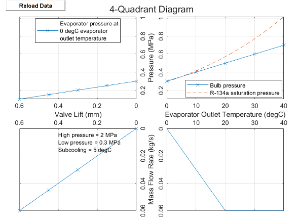
The diagram shows the four quadrants:

  • Quadrant 1: Plot of the fluid pressure of the sensing bulb versus the evaporator outlet temperature when the sensing bulb is attached to the evaporator outlet. In this image, the graph includes a second line that represents the vapor saturation curve of the refrigerant in the cycle, which is a plot of saturation pressure versus saturation temperature.

  • Quadrant 2: Plot of the valve lift versus the evaporator outlet pressure. The valve lift is the position of the needle of the valve. As the evaporator outlet pressure decreases, the valve opens and valve lift increases.

    When Valve parameterization is Tabulated data - quadrant diagram, the plot holds the evaporator outlet temperature constant at the Reference evaporator outlet temperature parameter value.

  • Quadrant 3: Plot of the mass flow rate through the valve versus valve lift.

    When Valve parameterization is Tabulated data - quadrant diagram, the plot holds the inlet pressure of the valve constant at the Reference condenser outlet pressure parameter, the inlet temperature constant at the Reference condenser subcooling parameter, and the outlet pressure constant at the Reference evaporator outlet pressure parameter.

  • Quadrant 4: Plot of the mass flow rate through the valve versus evaporator outlet temperature.

    When Valve parameterization is Tabulated data - quadrant diagram, the plot holds the inlet pressure of the valve constant at the Reference condenser outlet pressure parameter, the inlet temperature constant at the Reference condenser subcooling parameter, and the outlet pressure constant at the Reference evaporator outlet pressure parameter.

Tabulated Data Parameterization

When you set Valve parameterization to Tabulated data - quadrant diagram, the block uses tabulated data. Three of the four curves in the thermostatic expansion valve quadrant diagram specify the valve characteristics. The supplier typically provides this diagram.

To determine block characteristics, the block performs interpolation on the data you provide in the parameters Quadrant 1 - Evaporator outlet temperature vector, Quadrant 1 - Bulb pressure vector, Quadrant 2 - Valve lift vector, Quadrant 2 - Evaporator outlet pressure vector, Quadrant 3 - Valve lift vector, and Quadrant 3 - Mass flow rate vector.

The block determines the mass flow rate through the valve from the inlet pressure, outlet pressure, equalization pressure, and sensing bulb temperature by using the data from quadrant 1 to quadrant 3 and a series of interpolations. The block first calculates the quadrant 2 evaporator outlet pressure as

pevap,Q2=peqpbulb(Tbulb)+pbulb(Tevap,ref)

where:

  • peq depends on the valve pressure equalization setting:

    • When you set Pressure equalization to Internal pressure equalization, peq is the pressure at port B.

    • When you set Pressure equalization to External pressure equalization, peq is the pressure at port E.

  • pbulb(Tbulb) is the bulb fluid pressure interpolated at the bulb fluid temperature Tbulb. You specify the bulb fluid pressure data in the parameter Quadrant 1 – Bulb pressure vector.

  • pbulb(Tevap,ref) is the bulb fluid pressure interpolated at the reference evaporator outlet temperature Tevap,ref.

The block uses the valve lift data, L, from the Quadrant 2 – Valve lift vector parameter to interpolate the valve lift at the values in Quadrant 2 – Evaporator outlet pressure vector, which gives L = L(pevap,Q2). The block then uses the reference mass flow rate, m˙ref, from the Quadrant 3 – Mass flow rate vector, to interpolate the mass flow rate at the valve lift values m˙ref=m˙ref(L). The block scales the reference mass flow rate to the actual mass flow rate with

m˙=m˙ref2vinΔp(Δp2Δplam2)0.252vref(pcond,refpevap,ref)

where:

  • pcond,ref is the Reference condenser outlet pressure parameter.

  • pevap,ref is the Reference evaporator outlet pressure parameter.

  • vref is the specific volume that corresponds to the Reference condenser outlet pressure and Reference condenser subcooling parameters.

  • vin is the inlet specific volume, or the fluid volume per unit mass.

  • Δp is the pressure differential over the valve, pApB.

  • Δplam is the pressure threshold for transitional flow. Below this value, the flow is laminar. The block calculates this value as:

    Δplam=pA+pB2(1Blam),

    where Blam is the value of the Laminar flow pressure ratio parameter.

Pressure Equalization

The equalization pressure is the pressure at the evaporator outlet that governs valve operability. In physical systems with low pressure loss in the evaporator due to viscous friction, pressure equalization can occur internally with the pressure at port B. This is internal pressure equalization. In systems with larger losses, connect the evaporator outlet port to the valve block at port E.

Bulb Temperature Dynamics

You can model the bulb dynamic response to changing temperatures by selecting Bulb temperature dynamics. This introduces a first-degree lag in the measured temperature

dTbulbdt=TSTbulbτbulb,

where:

  • TS is the temperature at port S. If you do not model bulb dynamics, this value is Tbulb.

  • τbulb is the value of the Bulb thermal time constant parameter.

Fluid Specific Volume Dynamics

When the fluid at the valve inlet is a liquid-vapor mixture, the block calculates the specific volume as

vin=(1xdyn)vliq+xdynvvap,

where:

  • xdyn is the inlet vapor quality. The block applies a first-order lag to the inlet vapor quality of the mixture.

  • vliq is the liquid specific volume of the fluid.

  • vvap is the vapor specific volume of the fluid.

If the inlet fluid is liquid or vapor, vin is the respective liquid or vapor specific volume.

Vapor Quality Lag

If the inlet vapor quality is a liquid-vapor mixture, the block applies a first-order time lag

dxdyndt=xinxdynτ,

where:

  • xdyn is the dynamic vapor quality.

  • xin is the current inlet vapor quality.

  • τ is the value of the Inlet phase change time constant parameter.

If the inlet fluid is a subcooled liquid, xdyn is equal to xin.

Conservation Equations

Mass is conserved through the valve

m˙A+m˙B=0,

where:

  • m˙A is the mass flow rate at port A.

  • m˙B is the mass flow rate at port B.

The block supports reversed flows numerically, however, the valve block is not designed for flows from port B to port A.

The block conserves energy flow through the valve

ΦA+ΦB=0,

where:

  • ΦA is the energy flow rate at port A.

  • ΦB is the energy flow rate at port B.

Ports

Conserving

expand all

Valve inlet port. Connect this port to the outlet of a condenser or liquid receiver in a refrigeration cycle model.

Valve outlet port. Connect this port to the inlet of an evaporator in a refrigeration cycle model.

Two-phase fluid conserving port associated with the temperature of the sensing bulb. Connect this port to the outlet port of the evaporator. The valve operation depends on the comparison of the sensed temperature at S to the fluid saturation temperature.

There is no mass or energy flow rate through port S.

Two-phase fluid port associated with the pressure of the equalization line. Connect this port to the outlet port of the evaporator.

There is no mass or energy flow rate through port E.

Dependencies

To enable this port, set Pressure equalization to External pressure equalization.

Parameters

expand all

Method to determine valve characteristics. When you select Nominal capacity, superheat, and operating conditions, the valve provides the specified nominal capacity and superheat at the specified nominal operating conditions. When you select Tabulated data - quadrant diagram, you can specify the valve characteristics by using three of the four curves in a thermostatic expansion valve quadrant diagram.

Method to specify capacity for the evaporator. When you select Evaporator heat transfer, you can specify the nominal and maximum evaporator heat transfer values. When you select Mass flow rate, the block calculates the heat transfer based on the mass flow rate.

Dependencies

To enable this parameter, set Valve parameterization to Nominal capacity, superheat, and operating conditions.

Rate of heat transfer in the system evaporator under nominal operating conditions. This parameter sets the operational conditions of the thermostatic expansion valve.

Dependencies

To enable this parameter, set Valve parameterization to Nominal capacity, superheat, and operating conditions and Capacity specification to Evaporator Heat transfer.

Maximum rate of heat transfer in the system evaporator. In most refrigeration cycles, this value is 20% to 50% larger than the value of the Nominal evaporator heat transfer parameter. This parameter sets the maximum operating conditions for the thermostatic expansion valve.

Dependencies

To enable this parameter, set Valve parameterization to Nominal capacity, superheat, and operating conditions and Capacity specification to Evaporator Heat transfer.

Mass flow rate in the system evaporator under nominal operating conditions. The block uses this parameter to set the operational conditions of the thermostatic expansion valve.

Dependencies

To enable this parameter, set Valve parameterization to Nominal capacity, superheat, and operating conditions and Capacity specification to Mass flow rate.

Maximum rate of mass flow in the system evaporator. The block uses this parameter to set the maximum operating conditions for the thermostatic expansion valve.

Dependencies

To enable this parameter, set Valve parameterization to Nominal capacity, superheat, and operating conditions and Capacity specification to Mass flow rate.

Method to specify nominal pressure for the evaporator and condenser. When you select Specified pressure, you can specify the evaporator and condenser outlet pressure. When you select Pressure at specified saturation temperature, you specify the saturation temperature in the condenser and evaporator. The block calculates the corresponding saturation temperatures by using the refrigerant property tables.

Dependencies

To enable this parameter, set Valve parameterization to Nominal capacity, superheat, and operating conditions.

Refrigerant pressure in the condenser under nominal operating conditions. The block calculates the corresponding saturation temperatures by using the refrigerant property tables.

Dependencies

To enable this parameter, set Valve parameterization to Nominal capacity, superheat, and operating conditions and Nominal pressure specification to Specific pressure.

Refrigerant pressure in the evaporator under nominal operating conditions. The block calculates the corresponding saturation temperatures by using the refrigerant property tables.

Dependencies

To enable this parameter, set Valve parameterization to Nominal capacity, superheat, and operating conditions and Nominal pressure specification to Specific pressure.

Refrigerant saturation temperature in the condenser under nominal operating conditions.

Dependencies

To enable this parameter, set Valve parameterization to Nominal capacity, superheat, and operating conditions and Nominal pressure specification to Pressure at specified saturation temperature.

Refrigerant saturation temperature in the evaporator under nominal operating conditions.

Dependencies

To enable this parameter, set Valve parameterization to Nominal capacity, superheat, and operating conditions and Nominal pressure specification to Pressure at specified saturation temperature.

Difference between the value of the Nominal condensing (saturation) temperature parameter and the liquid temperature at the condenser outlet under nominal operating conditions.

Dependencies

To enable this parameter, set Valve parameterization to Nominal capacity, superheat, and operating conditions.

Difference between the superheated vapor temperature at the evaporator outlet and the value of the Nominal evaporating (saturation) temperature parameter under nominal operating conditions. The valve maintains this value by adjusting the open area to allow more or less fluid into the evaporator.

Dependencies

To enable this parameter, set Valve parameterization to Nominal capacity, superheat, and operating conditions.

Minimum allowed difference between the superheated vapor temperature at the evaporator outlet and the value of the Nominal evaporating (saturation) temperature parameter. If the operational difference falls below this value, the valve is closes.

Dependencies

To enable this parameter, set Valve parameterization to Nominal capacity, superheat, and operating conditions.

Whether to enable pressure limits in the evaporator. The options are:

  • Off: There is no pressure limit. The valve opens and closes based only on the evaporator superheat.

  • On - Specify maximum operating pressure: This setting places an upper limit on the evaporating pressure and temperature. The valve closes when the evaporator pressure reaches this limit.

  • On - Specify maximum operating temperature: This setting places an upper limit on the evaporating pressure and temperature. The valve closes when the evaporator temperature reaches this limit.

Dependencies

To enable this parameter, set Valve parameterization to Nominal capacity, superheat, and operating conditions.

Maximum permissible saturation pressure in the evaporator when evaporator pressure limiting is on.

Dependencies

To enable this parameter, set Valve parameterization to Nominal capacity, superheat, and operating conditions and set MOP limit to On - Specify maximum operating pressure.

Maximum permissible saturation temperature in the evaporator when evaporator temperature limiting is on.

Dependencies

To enable this parameter, set Valve parameterization to Nominal capacity, superheat, and operating conditions and set MOP limit to On - Specify maximum operating temperature.

Fraction of leakage-to-nominal flow through the valve when the valve is closed. A nonzero value enhances numerical stability in the fluid network.

Dependencies

To enable this parameter, set Valve parameterization to Nominal capacity, superheat, and operating conditions.

Continuous smoothing factor that introduces a layer of gradual change to the flow response when the valve is in near-open or near-closed positions. Set this value to a nonzero value less than one to increase the stability of your simulation in these regimes.

Dependencies

To enable this parameter, set Valve parameterization to Nominal capacity, superheat, and operating conditions.

Temperature of the sensing bulb, which is typically placed at the evaporator outlet. Therefore, this parameter is equivalent to the evaporator outlet temperature. The block uses this data on the x-axis in quadrant 1 of the four-quadrant diagram. This parameter must be the same length as the Quadrant 1 – Bulb pressure vector parameter.

Dependencies

To enable this parameter, set Valve parameterization to Tabulated data – quadrant diagram.

Pressure of the fluid inside the sensing bulb at the evaporator outlet. The refrigerant pressure at the evaporator outlet is independent of the internal fluid pressure of the sensing bulb. The valve uses the bulb pressure to open. The block interpolates this data for the y-axis in quadrant 1 of the four-quadrant diagram. This parameter must be the same length as the Quadrant 1 – Evaporator outlet temperature vector parameter.

Dependencies

To enable this parameter, set Valve parameterization to Tabulated data – quadrant diagram.

Vector of the valve lift, or the position of the needle of the valve. The block uses this data on the x-axis in quadrant 2 of the four-quadrant diagram. The valve lift must be defined consistently between quadrants 2 and 3. The block uses valve lift to relate the pressure in quadrant 2 and flow rate in quadrant 3. If data is unavailable, you can construct valve lift values, such as 0 for fully closed and 1 for fully open. This parameter must be the same length as the Quadrant 2 – Evaporator outlet pressure vector parameter.

Dependencies

To enable this parameter, set Valve parameterization to Tabulated data – quadrant diagram.

Vector of the equalization pressure, which is the measure of the evaporator outlet pressure of the valve. The valve uses the equalization pressure to close:

  • If the valve has internal pressure equalization, this parameter is the pressure at the outlet of the valve, which is connected to the evaporator inlet. In this case, the block assumes that the pressure loss in the evaporator is small.

  • If the valve has external pressure equalization, this is the value measured by the external pilot line connected to the evaporator outlet.

The block interpolates this data for the y-axis in quadrant 2 of the four-quadrant diagram. This parameter must be the same length as the Quadrant 2 – Valve lift vector parameter.

Dependencies

To enable this parameter, set Valve parameterization to Tabulated data – quadrant diagram.

Vector of the valve lift, or the position of the needle of the valve. The block uses this data on the x-axis in quadrant 3 of the four-quadrant diagram. The valve lift must be defined consistently between quadrants 2 and 3. The block uses valve lift to relate the pressure in quadrant 2 and flow rate in quadrant 3. If data is unavailable, you can construct valve lift values, such as 0 for fully closed and 1 for fully open. This parameter must be the same length as the Quadrant 3 – Mass flow rate vector parameter.

Dependencies

To enable this parameter, set Valve parameterization to Tabulated data – quadrant diagram.

Values of mass flow rate through the valve in relation to different values of the valve opening. The block interpolates this data for the y-axis in quadrant 3 of the four-quadrant diagram. This parameter must be the same length as the Quadrant 3 – Valve lift vector parameter. The first element corresponds to the leakage mass flow rate when the valve is closed. This value must be a positive, small value for numerical robustness.

Dependencies

To enable this parameter, set Valve parameterization to Tabulated data – quadrant diagram.

Reference valve inlet pressure. The block holds the valve inlet pressure at this value in quadrant 3 of the four-quadrant diagram.

Dependencies

To enable this parameter, set Valve parameterization to Tabulated data – quadrant diagram.

Reference evaporator outlet pressure. The block holds the evaporator outlet pressure at this value in quadrant 3 of the four-quadrant diagram.

Dependencies

To enable this parameter, set Valve parameterization to Tabulated data – quadrant diagram.

Reference evaporator outlet temperature. The block holds the evaporator outlet temperature at this value in quadrant 2 of the four-quadrant diagram.

Dependencies

To enable this parameter, set Valve parameterization to Tabulated data – quadrant diagram.

Difference in temperature between the condenser outlet and the condensing temperature. The block holds the valve inlet temperature at this value in quadrant 3 of the four-quadrant diagram.

Dependencies

To enable this parameter, set Valve parameterization to Tabulated data – quadrant diagram.

Pressure measurement location. Set this parameter to Internal pressure equalization to measure the evaporator pressure at port B. Set this parameter to External pressure equalization to expose the evaporator pressure port, E. Connect this port to an evaporator outlet. Choose the setting for this parameter depending on the design of your thermostatic expansion valve.

Whether to model thermal dynamics in temperature measurement. When you select this parameter, the bulb fluid temperature lags the refrigeration temperature. The Bulb thermal time constant parameter determines the lag response.

First-order time constant for the bulb fluid temperature delay. The block delays the measured temperature relative to the refrigerant temperature at port S. The time constant is proportional to the thermal mass of the bulb, including any ballast, and is inversely proportional to the thermal conductance across the thermal contact surface.

Dependencies

To enable this parameter, select Bulb temperature dynamics.

Cross-sectional area of connecting pipes at ports A and B.

Ratio of the evaporator outlet pressure to evaporator inlet pressure at which the fluid transitions between the laminar and turbulent regimes. The pressure loss corresponds to the mass flow rate linearly in laminar flows and quadratically in turbulent flows.

Time lag for liquid-vapor mixtures in computing the fluid specific volume. This parameter does not influence the specific volume when the inlet fluid is a fully supercooled liquid.

References

[1] Eames, Ian W., Adriano Milazzo, and Graeme G. Maidment. "Modelling Thermostatic Expansion Valves." International Journal of Refrigeration 38 (February 2014): 189-97.

Extended Capabilities

C/C++ Code Generation
Generate C and C++ code using Simulink® Coder™.

Version History

Introduced in R2020b

expand all