Heat Exchanger Interface (TL)
Thermal interface between a thermal liquid and its surroundings
Libraries:
Simscape /
Fluids /
Heat Exchangers /
Fundamental Components
Description
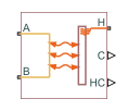
The Heat Exchanger Interface (TL) block represents a liquid interface in a thermal liquid network for heat transfer with other fluids. The block models the pressure drop and temperature change between the thermal liquid inlet and outlet of a thermal interface and when combined with the E-NTU Heat Transfer block models the heat transfer rate across the interface between two fluids.
Mass Balance
The form of the mass balance equation depends on the dynamic compressibility setting. If you clear the Enable dynamic compressibility checkbox, the mass balance equation is
where:
and are the mass flow rates into the interface through ports A and B.
If you select Enable dynamic compressibility, the mass balance equation is
where:
p is the pressure of the thermal liquid volume.
T is the temperature of the thermal liquid volume.
ɑ is the isobaric thermal expansion coefficient of the thermal liquid volume.
β is the isothermal bulk modulus of the thermal liquid volume.
ρ is the mass density of the thermal liquid volume.
V is the volume of thermal liquid in the heat exchanger interface.
Momentum Balance
The momentum balance in the heat exchanger interface depends on the fluid dynamic compressibility setting. If you select Enable dynamic compressibility, the momentum balance factors in the internal pressure of the heat exchanger interface explicitly. The momentum balance in the half volume between port A and the internal interface node is
while in the half volume between port B and the internal interface node it is
where:
pA and pB are the pressures at ports A and B.
p is the pressure in the internal node of the interface volume.
ΔpLoss,A and ΔpLoss,B are the pressure losses between port A and the internal interface node and between port B and the internal interface node.
If you clear the Enable dynamic compressibility checkbox, the momentum balance in the interface volume is computed directly between ports A and B as
Pressure Loss Calculations
The exact form of the pressure loss terms depends on the Pressure loss
model setting in the block dialog box. If the pressure loss model is set to
Pressure loss coefficient, the pressure loss in the half volume
adjacent to port A is
while in the half volume adjacent to port B it is
where:
μA and μB are the fluid dynamic viscosities at ports A and B.
CPLoss is the Pressure loss coefficient parameter specified in the block dialog box.
ReL is the Reynolds number upper bound for the laminar flow regime.
ReT is the Reynolds number lower bound for the turbulent flow regime.
Dh,p is the hydraulic diameter for pressure loss calculations.
ρA and ρB are the fluid mass densities at ports A and B.
SMin is the total minimum free-flow area.
If the pressure loss model is set to Correlation for flow inside
tubes, the pressure loss in the half volume adjacent to port
A is
while in the half volume adjacent to port B it is
where:
Lpress is the flow path length from inlet to outlet.
Ladd is the aggregate equivalent length of local resistances.
fT,A and fT,B are the turbulent-regime Darcy friction factors at ports A and B.
The Darcy friction factor in the half volume adjacent to port A is
while in the half volume adjacent to port B it is
where r is the internal surface absolute roughness.
If the pressure loss model is set to Tabulated data — Darcy friction
factor vs. Reynolds number, the pressure loss in the half volume adjacent to
port A is
while in the half volume adjacent to port B it is
where:
λ is the shape factor for laminar flow viscous friction.
f(ReA) and f(ReB) are the Darcy friction factors at ports A and B. The block obtains the friction factors from tabulated data specified relative to the Reynolds number.
If the pressure loss model is set to Tabulated data — Euler number
vs. Reynolds number, the pressure loss in the half volume adjacent to port
A is
while in the half volume adjacent to port B it is
where:
Eu(ReL) is the Euler number at the Reynolds number upper bound for laminar flows.
Eu(ReA) and Eu(ReB) are the Euler numbers at ports A and B. The block obtains the Euler numbers from tabulated data specified relative to the Reynolds number.
Energy Balance
The energy balance in the heat exchanger interface depends on the fluid dynamic compressibility setting. If you select Enable dynamic compressibility, the energy balance is
where:
U is the internal energy contained in the volume of the heat exchanger interface.
ϕA and ϕB are the energy flow rates through ports A and B into the volume of the heat exchanger interface.
QH is the heat flow rate through port H, representing the interface wall, into the volume of the heat exchange interface.
The internal energy derivatives are defined as
and
where u is the specific internal energy of the thermal liquid, or the internal energy contained in a unit mass of the same.
If you clear the Enable dynamic compressibility checkbox, the thermal liquid density is treated as a constant. The bulk modulus is then effectively infinite and the thermal expansion coefficient zero. The pressure and temperature derivatives of the compressible case vanish and the energy balance is restated as
where E is the total internal energy of the incompressible thermal liquid, or
The block calculates ρ from the Nominal liquid temperature and Nominal liquid pressure parameters.
Heat Transfer Correlations
The block calculates and outputs the liquid-wall heat transfer coefficient value. The
calculation depends on the Heat transfer coefficient specification
setting in the block dialog box. If the heat transfer coefficient specification is
Constant heat transfer coefficient, the heat transfer
coefficient is simply the constant value specified in the block dialog box,
where:
hL-W is the liquid-wall heat transfer coefficient.
hConst is the Liquid-wall heat transfer coefficient value specified in the block dialog box.
For all other heat transfer coefficient parameterizations, the heat transfer coefficient is defined as the arithmetic average of the port heat transfer coefficients:
where:
hA and hB are the liquid-wall heat transfer coefficients at ports A and B.
The heat transfer coefficient at port A is
while at port B it is
where:
NuA and NuB are the Nusselt numbers at ports A and B.
kA and kB are the thermal conductivities at ports A and B.
Dh,heat is the hydraulic diameter for heat transfer calculations.
The hydraulic diameter used in heat transfer calculations is defined as
where:
Lheat is the flow path length used in heat transfer calculations.
Sheat is the total heat transfer surface area.
Nusselt Number Calculations
The Nusselt number calculation depends on the Heat transfer coefficient
specification setting in the block dialog box. If the heat transfer
specification is set to Correlation for flow inside tubes, the
Nusselt number at port A is
while at port B it is
where:
NuL is the Nusselt number for laminar flow heat transfer value specified in the block dialog box.
PrA and PrB are the Prandtl numbers at ports A and B.
If the heat transfer specification is set to Tabulated data —
Colburn data vs. Reynolds number, the Nusselt number at port
A is
while at port B it is
where:
j(ReA,heat) and j(ReB,heat) are the Colburn numbers at ports A and B. The block obtains the Colburn numbers from tabulated data provided as a function of the Reynolds number.
ReA,heat and ReB,heat are the Reynolds numbers based on the hydraulic diameters for heat transfer calculations at ports A and B. This parameter is defined at port A as
and at port B as
If the heat transfer specification is set to Tabulated data —
Nusselt number vs. Reynolds number and Prandtl number, the Nusselt number at
port A is
while at port B it is