Main Content

3-Zone Pipe (2P)

Conduit for the transport of a phase-changing fluid with heat transfer

Since R2018b

  • 3-Zone Pipe (2P) block

Libraries:
Simscape / Fluids / Two-Phase Fluid / Pipes & Fittings

Description

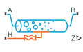
The 3-Zone Pipe (2P) block models a pipe with a phase-changing fluid. Each fluid phase is called a zone, which is a fractional value between 0 and 1. Zones do not mix. The block uses a boundary-following model to track the sub-cooled liquid (L), vapor-liquid mixture (M), and super-heated vapor (V) in three zones. The relative amount of space a zone occupies in the system is called a zone length fraction within the system.

Port H is a thermal port that represents the environmental temperature. The rate of heat transfer between the fluid and the environment depends on the fluid phase of each zone. The pipe wall is modeled within the block and the pipe wall temperature in each zone may be different. The pressure and temperature are influenced by fluid dynamic compressibility and the fluid zone thermal capacity.

Heat Transfer Between the Fluid and the Wall

The convective heat transfer coefficient between the fluid and the wall, αF, varies per zone according to the Nusselt number:

αF=NukDH,

where:

  • Nu is the zone Nusselt number.

  • k the average fluid thermal conductivity.

  • DH is the pipe Hydraulic diameter, the equivalent diameter of a non-circular pipe.

The Nusselt number used in the heat transfer coefficient is the greater of the turbulent- and laminar-flow Nusselt numbers.

For turbulent flows in the subcooled liquid or superheated vapor zones, the Nusselt number is calculated with the Gnielinski correlation:

Nu=f8(Re1000)Pr1+12.7( f8)1/2(Pr2/31),

where:

  • Re is the zone average Reynolds number.

  • Pr is the zone average Prandtl number.

  • f is the Darcy friction factor, calculated from the Haaland correlation:

    1f=1.8log[(εDH3.7)1.11+6.9Re],

    where ε is the wall Internal surface absolute roughness.

For turbulent flows in the liquid-vapor mixture zone, the Nusselt number is calculated with the Cavallini-Zecchin correlation:

Nu=aReSLbPrSLc{[(ρSLρSV1)xOut+1]1+b[(ρSLρSV1)xIn+1]1+b}(1+b)(ρSLρSV1)(xOutxIn).

Where:

  • ReSL is the Reynolds number of the saturated liquid.

  • PrSL is the Prandtl number of the saturated liquid.

  • ρSL is the density of the saturated liquid.

  • ρSV is the density of the saturated vapor.

  • a= 0.05, b = 0.8, and c= 0.33.

When fins are modeled on the pipe internal surface, the heat transfer coefficient is:

αF=NukDH(1+ηIntsInt),

where:

  • ηInt is the Internal fin efficiency.

  • sInt is the Ratio of internal fins surface area to no-fin surface area.

For laminar flows, the Nusselt number is set by the Laminar flow Nusselt number parameter.

Empirical Nusselt Number Formulation

When the Heat transfer coefficient model parameter is Colburn equation, the block calculates the Nusselt number for the subcooled liquid and superheated vapor zones by using the empirical Colburn equation

Nu=aRebPrc,

where a, b, and c are values in the Coefficients [a, b, c] for a*Re^b*Pr^c in liquid zone and Coefficients [a, b, c] for a*Re^b*Pr^c in vapor zone parameters.

The block calculates the Nusselt number for liquid-vapor mixture zones by using the Cavallini-Zecchin equation with the variables in the Coefficients [a, b, c] for a*Re^b*Pr^c in mixture zone parameter.

Specific Enthalpy

The heat transfer rate from the fluid is based on the change in specific enthalpy in each zone:

Q=m˙Q(ΔhL+ΔhM+ΔhV),

where m˙Q is the mass flow rate for heat transfer. It is the pipe inlet mass flow rate, either m˙A or m˙B, depending on the direction of fluid flow.

In the liquid and vapor zones, the change in specific enthalpy is defined as:

Δh=cp(THTI)[1exp(zSWm˙Qcp(αF1+αE1))],

where:

  • cp is the specific heat of the liquid or vapor.

  • TH is the environmental temperature.

  • TI is the liquid inlet temperature.

  • z is the fluid zone length fraction.

  • αE is the heat transfer coefficient between the wall and the environment.

  • SW is wall surface area:

    SW=4ADHL,

    where:

    • A is the pipe Cross-sectional area.

    • L is the Pipe length.

    Note that this wall surface area does not include fin area, which is defined in the Ratio of external fins surface area to no-fin surface area and Ratio of internal fins surface area to no-fin surface area parameters. Fins are set in proportion to the wall surface area. A value of 0 means there are no fins on the pipe wall.

In the liquid-vapor mixture zone, the change in specific enthalpy is calculated as:

Δh=(THTS)zSWm˙Q(αF1+αE1),

where TS is the fluid saturation temperature. It is assumed that the liquid-vapor mixture is always at this temperature.

Heat Transfer Rate

The total heat transfer between the fluid and the pipe wall is the sum of the heat transfer in each fluid phase:

QF=QF,L+QF,V+QF,M.

The heat transfer rate between the fluid and the pipe in the liquid zone is:

QF,L=m˙Qcp,L[TW,Lmin(TI,TS)][1exp(zLSWαLm˙Qcp,L)].

where TW,L is the temperature of the wall surrounding the liquid zone.

The heat transfer rate between the fluid and the pipe in the mixture zone is:

QF,M=(THTSat)zMSWαM.

The heat transfer rate between the fluid and the pipe in the vapor zone is:

QF,V=m˙Qcp,V[TW,Vmin(TI,TSat)][1exp(zVSWαVm˙Qcp,V)],

where TW,V is the temperature of the wall surrounding the vapor zone.

Heat Transfer Between the Wall and the Environment

If the pipe wall has a finite thickness, the heat transfer coefficient between the wall and the environment, αE, is defined by:

1αE=1αW+1αExt(1+ηExtsExt),

where αW is the heat transfer coefficient due to conduction through the wall:

αW=kWDHln(1+tWDH),

and where:

  • kW is the Wall thermal conductivity.

  • tW is the Wall thickness .

  • αExt is the External environment heat transfer coefficient.

  • ηExt is the External fin efficiency.

  • sExt is the Ratio of external fins surface area to no-fin surface area.

If the wall does not have thermal mass, the heat transfer coefficient between the wall and environment equals the heat transfer coefficient of the environment, αExt.

Heat Transfer Rate

The heat transfer rate between each wall zone and the environment is:

QH,zone=(THTW)zSWαE.

The total heat transfer between the wall and the environment is:

QH=QH,L+QH,V+QH,M.

Governing Differential Equations

The heat transfer rate depends on the thermal mass of the wall, CW:

CW=cp,WρWSW(tW+tW2DH),

where:

  • cp,W is the Wall specific heat.

  • ρW is the Wall density.

The governing equations for heat transfer between the fluid and the external environment are, for the liquid zone:

QH,LQF,L=CW[zLdTW,Ldt+max(dzLdt,0)(TW,LTW,M)],

for the mixture zone:

QH,MQF,M=CW[zMdTW,Mdt+min(dzLdt,0)(TW,LTW,M)+min(dzVdt,0)(TW,VTW,M)],

and for the vapor zone:

QH,VQF,V=CW[zVdTW,Vdt+max(dzVdt,0)(TW,VTW,M)].

Momentum Balance

The pressure differential over the pipe consists of two factors: changes in pressure due to changes in density, and changes in pressure due to friction at the pipe walls.

For turbulent flows, when the Reynolds number is above the Turbulent flow lower Reynolds number limit, pressure loss is calculated in terms of the Darcy friction factor. The pressure differential between port A and the internal node I is:

pApI=(1ρI1ρA*)(m˙AS)2+fAm˙A|m˙A|2ρIDHS2(L+LAdd2),

where:

  • ρI is the fluid density at internal node I.

  • ρA* is the fluid density at port A. This is the same as ρA when the flow is steady-state; when the flow is transient, it is calculated from the fluid internal state with the adiabatic expression:

    uA*+pAρA*+12(m˙AρA*S)2=h+12(m˙AρS)2,

    where:

    • h is the average specific enthalpy, h=hLzL+hVzV+hMzM.

    • ρ is the average density, ρ=ρLzL+ρMzM+ρVzV.

    This is due to the fact that heat transfer calculation takes place at the internal node I.

  • m˙A is the mass flow rate through port A.

  • L is the Pipe length.

  • LAdd is the Aggregate equivalent length of local resistances, which is the equivalent length of a tube that introduces the same amount of loss as the sum of the losses due to other local resistances.

Note that the Darcy friction factor is dependent on the Reynolds number, and is calculated at both ports.

The pressure differential between port B and internal node I is:

pBpI=(1ρI1ρB*)(m˙BS)2+fBm˙B|m˙B|2ρIDHS2(L+LAdd2).

where:

  • ρB* is the fluid density at port B. This is the same as ρB when the flow is steady-state; when the flow is transient, it is calculated from the fluid internal state with the adiabatic expression:

    uB*+pBρB*+12(m˙BρB*S)2=h+12(m˙BρS)2.

  • m˙B is the mass flow rate through port B.

For laminar flows, when the Reynolds number is below the Laminar flow upper Reynolds number limit, the pressure loss due to friction is calculated in terms of the Laminar friction constant for Darcy friction factor, λ. The pressure differential between port A and internal node I is:

pApI=(1ρI1ρA*)(m˙AS)2+λμm˙A2ρIDH2S(L+LAdd2),

where μ is the average fluid dynamic viscosity:

μ=μLzL+μMzM+μVzV.

The pressure differential between port B and internal node I is:

pBpI=(1ρI1ρB*)(m˙BS)2+λμm˙B2ρIDH2S(L+LAdd2).

For transitional flows, the pressure differential due to viscous friction is a smoothed blend between the values for laminar and turbulent pressure losses.

Mass Balance

The total mass accumulation rate is defined as:

dMdt=m˙A+m˙B,

where M is the total fluid mass in the pipe. In terms of fluid zones, the mass accumulation rate is a function of the change in density, ρ, with respect to pressure, p, and the fluid specific internal energy, u:

dMdt=[(ρp)udpdt+(ρu)pduoutdt+ρLdzLdt+ρMdzMdt+ρVdzVdt]V,

where:

  • uout is the specific internal energy after all heat transfer has occurred.

  • V is the total fluid volume, or the volume of the pipe.

Energy Balance

The energy conservation equation is:

Mduoutdt+(m˙A+m˙B)uout=ϕA+ϕB+QF,

where:

  • ϕA is the energy flow rate at port A.

  • ϕB is the energy flow rate at port B.

  • QF is the heat transfer rate between the fluid and the wall.

Assumptions and Limitations

  • The pipe wall is perfectly rigid.

  • The flow is fully developed. Friction losses and heat transfer do not include entrance effects.

  • Fluid inertia is negligible.

  • The effect of gravity is negligible.

  • When the pressure is above the fluid critical pressure, large values of thermal fluid properties (such as Prandtl number, thermal conductivity, and specific heat) may not accurately reflect the heat exchange in the pipe.

Ports

Output

expand all

Vector with the length fractions of the liquid, mixed-phase, and vapor zones in the pipe.

Conserving

expand all

Opening through which the two-phase fluid flows into or out of the pipe. Ports A and B can each function as either inlet or outlet. Thermal conduction is allowed between the two-phase fluid ports and the fluid internal to the pipe (though its impact is typically relevant only at near zero flow rates).

Opening through which the two-phase fluid flows into or out of the pipe. Ports A and B can each function as either inlet or outlet. Thermal conduction is allowed between the two-phase fluid ports and the fluid internal to the pipe (though its impact is typically relevant only at near zero flow rates).

Thermal boundary condition at the outer surface of the pipe wall. Use this port to capture heat exchange of various kinds—for example, conductive, convective, or radiative—between the pipe wall and the environment. Heat exchange between the inner surface of the wall and the fluid is captured directly in the block.

Parameters

expand all

Geometry

Distance between the ports of the pipe. The liquid, two-phase, and vapor zones each comprise a fraction of this distance. The zone fractions can vary but their aggregate length, being the same as the distance of the pipe, is fixed.

Internal area of the pipe normal to the direction of flow. The cross section of the pipe is assumed to be constant throughout its length.

Ratio of the opening area of a cross section of the pipe to the perimeter of that area. The pipe is not required to be cylindrical, and its cross-section have any shape. This parameter gives the diameter that a general cross section would have if it were circular.

Viscous Friction

Combined length of all local resistances present in the pipe. Local resistances include bends, fittings, armatures, and pipe inlets and outlets. The effect of the local resistances is to increase the effective length of the pipe. This length is added to the geometrical pipe length for friction calculations.

Average depth of all surface defects on the internal surface of the pipe. The surface defects affect the pressure loss across the pipe in the turbulent flow regime.

Reynolds number above which the pipe flow begins to transition from laminar to turbulent. This value is the maximum Reynolds number corresponding to fully developed laminar flow.

Reynolds number below which the pipe flow begins to transition from turbulent to laminar. This value is the minimum Reynolds number corresponding to fully developed turbulent flow.

Dimensionless factor used to capture the effects of cross-sectional geometry on the viscous friction losses incurred in the laminar flow regime. Typical values are 64 for a circular cross section, 57 for a square cross section, and 62 for a rectangular cross section with an aspect ratio of 2.

Heat Transfer

Heat transfer coefficient for heat exchange between the environment (at port H) and the outer surface of the pipe wall. If this parameter is set to inf, then the thermal resistance between the environment and the wall is assumed to be zero. The pipe wall then has a uniform temperature equal to that associated with port H.

Average thickness of the pipe wall material. If this value is set to 0, then both thermal resistance due to conduction through the pipe wall and thermal storage due to the thermal mass of the pipe wall are assumed to be negligible.

Thermal conductivity of the pipe wall material. If this parameter is set to inf, then thermal resistance due to conduction through the pipe wall is assumed to be negligible.

Heat capacity per unit mass of the pipe wall material. If this parameter is set to 0, then thermal storage due to the thermal mass of the pipe is assumed to be negligible.

Mass density of the pipe wall material. If this parameter is set to 0, then thermal storage due to the thermal mass of the pipe wall is assumed to be negligible.

Ratio of the total heat transfer surface area of the fins on the external side of the pipe wall to that of the pipe wall without any fins. The presence of fins serves to enhance the convective heat transfer between the pipe wall and the environment.

Ratio of the actual heat exchange rate between the external fins and the environment to its ideal value (if the fins were entirely held at the temperature of the pipe wall). This parameter is a function of fin geometry.

Ratio of the total heat transfer surface area of the fins on the internal side of the pipe wall to that of the pipe wall without any fins. The presence of fins serves to enhance the convective heat transfer between the pipe wall and the fluid.

Ratio of the actual heat exchange rate between the internal fins and the environment to its ideal value (if the fins were entirely held at the temperature of the pipe wall). This parameter is a function of fin geometry.

Method of calculating the heat transfer coefficient between the fluid and the wall. The available settings are:

  • Colburn equation. Use this setting to calculate the heat transfer coefficient with user-defined variables a, b, and c. In the liquid and vapor zones, the heat transfer coefficient is based on the Colburn equation. In the liquid-vapor mixture zone, the heat transfer coefficient is based on the Cavallini-Zecchin equation.

  • Correlation for flow inside tubes. Use this setting to calculate the heat transfer coefficient for pipe flows. In the liquid and vapor zones, the heat transfer coefficient is calculated with the Gnielinski correlation. In the liquid-vapor mixture zone, the heat transfer coefficient is calculated with the Cavallini-Zecchin equation.

Three-element vector that contains the empirical coefficients of the Colburn equation. Each fluid zone has a distinct Nusselt number, which the block calculates by using the Colburn equation for each zone. The general form of the Colburn equation is:

Nu=aRebPrc.

Dependencies

To enable this parameter, set Heat transfer coefficient model to Colburn equation.

Three-element vector that contains the empirical coefficients for the Cavallini-Zecchin equation. Each fluid zone has a distinct Nusselt number, which the block calculates in the mixture zone by using the Cavallini-Zecchin equation:

Nu=aReSLbPrSLc{[(ρSLρSV1)xOut+1]1+b[(ρSLρSV1)xIn+1]1+b}(1+b)(ρSLρSV1)(xOutxIn).

Dependencies

To enable this parameter, set Heat transfer coefficient model to Colburn equation.

Three-element vector that contains the empirical coefficients of the Colburn equation. Each fluid zone has a distinct Nusselt number, which the block calculates by using the Colburn equation for each zone. The general form of the Colburn equation is:

Nu=aRebPrc.

Dependencies

To enable this parameter, set Heat transfer coefficient model to Colburn equation.

Ratio of convective to conductive heat exchange rates in the laminar flow regime. This parameter is a function of pipe cross section geometry. Typical values are 3.66 for a circular cross section, 2.98 for a square cross section, and 3.39 for a rectangular cross section with an aspect ratio of 2.

Effects and Initial Conditions Tab

Thermodynamic variable in terms of which to define the initial conditions of the component.

The value for Initial fluid energy specification limits the available initial states for the two-phase fluid. When Initial fluid energy specification is:

  • Temperature — Specify an initial state that is a subcooled liquid or superheated vapor. You cannot specify a liquid-vapor mixture because the temperature is constant across the liquid-vapor mixture region.

  • Vapor quality — Specify an initial state that is a liquid-vapor mixture. You cannot specify a subcooled liquid or a superheated vapor because the liquid mass fraction is 0 and 1, respectively, across the whole region. Additionally, the block limits the pressure to below the critical pressure.

  • Vapor void fraction — Specify an initial state that is a liquid-vapor mixture. You cannot specify a subcooled liquid or a superheated vapor because the liquid mass fraction is 0 and 1, respectively, across the whole region. Additionally, the block limits the pressure to below the critical pressure.

  • Specific enthalpy — Specify the specific enthalpy of the fluid. The block does not limit the initial state.

  • Specific internal energy — Specify the specific internal energy of the fluid. The block does not limit the initial state.

Pressure in the pipe at the start of simulation, specified against absolute zero.

Fluid temperature in the pipe at the start of simulation. This parameter can be a scalar or a 2-element vector. If it is a scalar, the initial temperature is assumed to be uniform throughout the pipe. If it is a vector, the initial temperature is assumed to vary linearly between the ports. The first vector element gives the initial temperature at the inlet and the second vector element that at the outlet.

Dependencies

This parameter is active when the Initial fluid energy specification option is set to Temperature.

Vapor quality, or mass fraction of vapor, in the pipe at the start of simulation. This parameter can be a scalar or a 2-element vector. If it is a scalar, the initial vapor quality is assumed to be uniform throughout the pipe. If it is a vector, the initial vapor quality is assumed to vary linearly between the ports. The first vector element gives the initial vapor quality at the inlet and the second vector element that at the outlet.

Dependencies

This parameter is active when the Initial fluid energy specification option is set to Vapor quality.

Vapor void fraction, or vapor volume fraction, in the pipe at the start of simulation. This parameter can be a scalar or a 2-element vector. If it is a scalar, the initial vapor void fraction is assumed to be uniform throughout the pipe. If it is a vector, the initial vapor void fraction is assumed to vary linearly between the ports. The first vector element gives the initial vapor void fraction at the inlet and the second vector element that at the outlet..

Dependencies

This parameter is active when the Initial fluid energy specification option is set to Vapor void fraction.

Specific enthalpy of the fluid in the pipe at the start of simulation. This parameter can be a scalar or a 2-element vector. If it is a scalar, the initial specific enthalpy is assumed to be uniform throughout the pipe. If it is a vector, the initial specific enthalpy is assumed to vary linearly between the ports. The first vector element gives the initial specific enthalpy at the inlet and the second vector element that at the outlet.

Dependencies

This parameter is active when the Initial fluid energy specification option is set to Specific enthalpy.

Specific internal energy of the fluid in the pipe at the start of simulation. This parameter can be a scalar or a 2-element vector. If it is a scalar, the initial specific internal energy is assumed to be uniform throughout the pipe. If it is a vector, the initial specific internal energy is assumed to vary linearly between the ports. The first vector element gives the initial specific internal energy at the inlet and the second vector element that at the outlet.

Dependencies

This parameter is active when the Initial fluid energy specification option is set to Specific internal energy.

References

[1] White, F.M., Fluid Mechanics, 7th Ed, Section 6.8. McGraw-Hill, 2011.

[2] Çengel, Y.A., Heat and Mass Transfer—A Practical Approach, 3rd Ed, Section 8.5. McGraw-Hill, 2007.

Extended Capabilities

C/C++ Code Generation
Generate C and C++ code using Simulink® Coder™.

Version History

Introduced in R2018b

expand all