Use Callback Functions in Custom Reference Design
This example illustrates how to customize the reference design dynamically by using a callback function based on the reference design parameter options. Also, this example shows how you can customize the number of AXI4-Stream interface channels in your reference design to be Only AXI4-Stream Master interface, Only AXI4-Stream Slave interface or both the interfaces.
Prerequisites
To run this example, you must have the following software and hardware installed and set up:
HDL Coder™ Support Package for AMD® FPGA and SoC Devices
Embedded Coder® Support Package for Xilinx® Zynq® Platform
Xilinx® Vivado® Design Suite, with supported version listed in HDL Language Support and Supported Third-Party Tools and Hardware
Xilinx® Zynq®-7000 SoC ZC706 Evaluation Kit
Latest SD image from ECoder support package setup wizard
Introduction
Instead of creating multiple reference designs that have different interface choices, data widths, or I/O plugins now you have an option of creating one reference design that has different interface choices or data widths as parameters. You can use the CustomizeReferenceDesignFcn method to reference the callback function that has different choices for interfaces or data widths in your reference design. For example, you can create one reference design and select the reference design parameter choice that has only AXI4-Stream Master or only AXI4-Stream Slave or both AXI4-Stream Master and AXI4-Stream Slave interfaces instead of creating three separate reference designs.
Create Reference Design Definition File and Callback Function
For this demo, you can consider Xilinx® Zynq® ZC706 AXI4-Stream reference design which consists of two Xilinx® AXI DMAs to handle the data transfer from Processor to FPGA and vice versa using AXI4-Stream Master and Slave interfaces. In this example you customize the number of AXI4-Stream interface channels with a single reference design by creating a callback function. The different interface channels in the callback code shown below uses the different device tree. Similarly, you can modify your created reference design definition file to select different reference design parameter choices using the callback function.
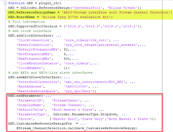
The picture below shows the Stream_Channel reference design parameter and interface choices for the AXI4-Stream interface with Stream channel Selection reference design specified by using the addParameter method. The CustomizeReferenceDesignFcn method references a callback function that has the name callback_CustomizeReferenceDesign.
The code below shows the callback function callback_CustomizeReferenceDesign that has the AXI4-Stream Master or Slave Channels or both channels specified by using the addAXI4StreamInterface method. The DeviceTreeName method shown below in the callback is to specify the device tree file, which is different for different stream channels.
function callback_CustomizeReferenceDesign(infoStruct)
% Reference design callback run at the end of the task Set Target Reference Design
% infoStruct: information in structure format
% infoStruct.ReferenceDesignObject: current reference design registration object
% infoStruct.BoardObject: current board registration object
% infoStruct.ParameterStruct: custom parameters of the current reference design, in struct format
% infoStruct.HDLModelDutPath: the block path to the HDL DUT subsystem
% infoStruct.ReferenceDesignToolVersion: Reference design Tool Version set in 1.2 Task
hRD = infoStruct.ReferenceDesignObject;
paramStruct = infoStruct.ParameterStruct;
% get the reference design parameter value
ParamValue = paramStruct.StreamChanel;
% Add the reference design interface into interface list table baed on the
% reference design Parameter value
if strcmp(ParamValue, 'Both Master & Slave')
 % add custom Vivado design
 hRD.addCustomVivadoDesign( ...
     'CustomBlockDesignTcl', 'system_top.tcl', ...
     'VivadoBoardPart',      'xilinx.com:zc706:part0:1.0');
 hRD.addAXI4StreamInterface( ...
     'MasterChannelEnable',      true, ...
     'SlaveChannelEnable',       true, ...
     'MasterChannelConnection', 'axi_dma_s2mm/S_AXIS_S2MM', ...
     'SlaveChannelConnection',  'axi_dma_mm2s/M_AXIS_MM2S', ...
     'MasterChannelDataWidth',   32, ...
     'SlaveChannelDataWidth',    32, ...
     'HasDMAConnection',         true);
 hRD.DeviceTreeName = 'devicetree_axistream_iio.dtb';
elseif strcmp(ParamValue, 'Master Only')
 % Block design TCl for Master Only reference design
 hRD.addCustomVivadoDesign( ...
     'CustomBlockDesignTcl', 'system_top_masteronly.tcl', ...
     'VivadoBoardPart',      'xilinx.com:zc706:part0:1.0');
  hRD.addAXI4StreamInterface( ...
      'MasterChannelEnable',      true, ...
      'SlaveChannelEnable',       false, ...
      'MasterChannelConnection', 'axi_dma_s2mm/S_AXIS_S2MM', ...
      'MasterChannelDataWidth',   32, ...
      'HasDMAConnection',         true);
  hRD.DeviceTreeName = 'devicetree_axistream_MasterOnly_iio.dtb';
elseif strcmp(ParamValue, 'Slave Only') % Block design TCl for Slave Only reference design hRD.addCustomVivadoDesign( ... 'CustomBlockDesignTcl', 'system_top_slaveonly.tcl', ... 'VivadoBoardPart', 'xilinx.com:zc706:part0:1.0');
% add AXI4-Stream Slave only interface
hRD.addAXI4StreamInterface( ...
'MasterChannelEnable', false, ...
'SlaveChannelEnable', true, ...
'SlaveChannelConnection', 'axi_dma_mm2s/M_AXIS_MM2S', ...
'SlaveChannelDataWidth', 32, ...
'HasDMAConnection', true);
hRD.DeviceTreeName = 'devicetree_axistream_SlaveOnly_iio.dtb';
end
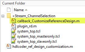
endSo, create the callback function like as shown above and pass the infoStruct argument to the callback function. The argument contains reference design customization information in a structure format. Save the created callback function in the reference design folder like as shown below or you can save anywhere and add the file to MATLAB path.
Generate HDL IP core with Only AXI4-Stream Master/Only AXI4-Stream Slave Interface
1.Set up the Xilinx® Vivado® synthesis tool path using the hdlsetuptoolpath command in the MATLAB(r) command window. Use your own Vivado® installation path when you run the command.
hdlsetuptoolpath('ToolName', 'Xilinx Vivado', 'ToolPath', vivadopath);
2. Add the demo reference design folder to the MATLAB path using following command:
example_root = (hdlcoder_amd_examples_root)
cd (example_root)
addpath(genpath('ZC706');
3. Open AXI4-Stream Master only model using following command:
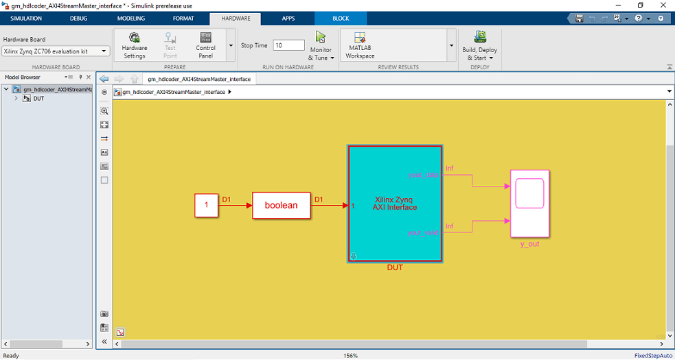
open_system('hdlcoder_AXI4StreamMaster');
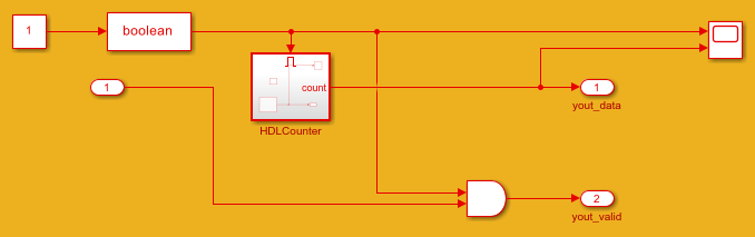
The DUT is the hardware subsystem targeting the FPGA fabric. Inside this DUT, the HDL Counter subsystem acts as master. This counter counts from 1 to 50 and is connected to yout_data output signal which is mapped to AXI4-Stream master interface.
You can also use AXI4 Slave only model. Use the following command to open the model:
open_system('hdlcoder_AXI4StreamSlave');
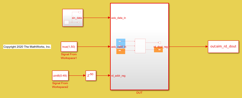
As shown above DUT has a Dual Port RAM which acts as slave and receives data using AXI4-Stream Slave interface through axis_data_in input signal.
4. Start the HDL Workflow Advisor from the DUT subsystem, hdlcoder_AXI4StreamMaster/DUT for AXI4-Stream Master only demo. Similarly Open HDL Workflow Advisor from the DUT subsystem, hdlcoder_AXI4StreamSlave/DUT for AXI4-Stream Slave only demo.
The target interface settings are already saved for ZC706 in these models, so the settings in Task 1.1 to 1.3 are automatically loaded. In Task 1.1, IP Core Generation is selected for Target workflow, and Xilinx Zynq ZC706 evaluation kit is selected for Target platform. In task 1.2, AXI4-Stream interface with Stream channel Selection is selected for reference design. Select Stream Channel reference design parameter choice as Master Only for AXI4-Stream Master only demo and choose Slave Only as parameter choice for AXI4-Stream Slave only demo.
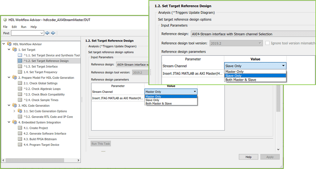
As shown in the figure above you can customize the reference design to Only AXI4-Stream Master or Only Slave or both AXI4-Stream Master and Slave by selecting the Stream Channel reference design parameter choice. Callback function with corresponding Tcl gets evaluated at the end of the Set Target Reference Design task.
5. If the parameter choice selected as Master Only, then the interface choice in task 1.3 shows as AXI4 Stream Master. Here, the AXI4-Stream interface communicates in master mode and sends data to AXI4_Stream Slave IP through yout_data signal. Similarly, If Slave Only parameter choice is selected, then the interface choice shows as AXI4 Stream Slave. Where, the AXI4-Stream interface communicates in slave mode and receives data through axis_data_in signal as shown below.

6. Right-click task 4.1, Create Project, and select Run to Selected Task to insert the generated IP core into the AXI4-Stream interface with Stream channel Selection reference design. The reference design contains Xilinx AXI DMA IP to handle the data streaming between FPGA fabric and processor or vice versa based on the reference design interface either Only AXI4-Stream master or only AXI4-Stream Slave.
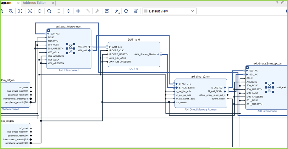
Following diagram shows the generated vivado project with AXI4-Stream Master only interface choice, and you can see the connection between HDL coder generated DUT IP and slave to memory mapped Xilinx AXI DMA IP. In this reference design, DMA Controller reads the data from FPGA IP.
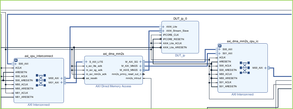
Similarly, following diagram shows the generated vivado project with AXI4-Stream Slave only interface choice, where the FPGA IP receives streaming data from DMA Controller.
7. In the HDL Workflow Advisor, run the rest of the tasks to generate the software interface model, and build and download the FPGA bitstream.
Generate ARM executable Using AXI4-Stream Driver Block for AXI4-Stream Master only reference design
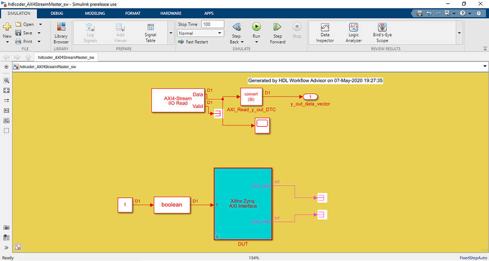
A software interface model is generated in Task 4.2, Generate Software Interface Model, as shown in the following picture.
The AXI4-Stream IIO driver block cannot be automatically generated in the software interface model when a scalar port yout_data is mapped to AXI4-Stream interface "AXI4-Stream Master". Before you generate code from the software interface model, add the AXI4-Stream IIO Read driver block from the Embedded Coder Support Package for Xilinx Zynq Platform Library in the Simulink Library Browser.
The updated software interface model for AXI4-Stream Master only reference designs are provided:
open_system('hdlcoder_AXI4StreamMaster_sw.slx')
Continuous data of count 0 to 50 is used in this model, and is connected to AXI4 Stream DMA driver block.
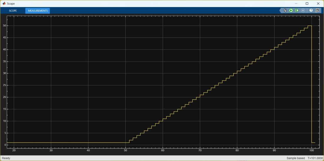
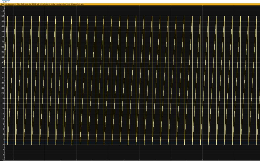
Click the Monitor & Tune button on the Hardware tab of Simulink Toolstrip. Embedded Coder builds the model, downloads the ARM executable to the Zc706 hardware. Now, both the hardware and software parts of the design are running on Zynq hardware. The FPGA IP sends the source data through the DMA controller and the AXI4-Stream interface. The ARM processor receives the data from the FPGA IP, and sends the result data to Simulink via external mode. Observe the output from the Zynq hardware on the time Scope y_out.
Generate ARM executable Using AXI4-Stream Driver Block for AXI4-Stream Slave only reference design
The updated software interface model for only AXI4-Stream Slave reference design is provided:
open_system('hdlcoder_AXI4StreamSlave_sw.slx')
In this model, a counter block which generates 1 to 50 incremental data is connected to AXI4-Stream Write DMA driver block. This means the DMA controller will stream count data samples to the HDL IP core via the AXI4-Stream Slave interface.
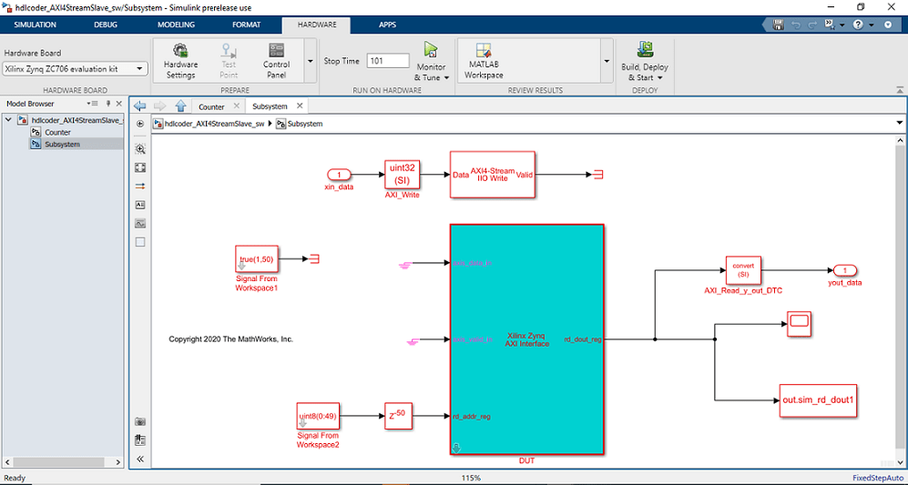
Click the Monitor & Tune button on the Hardware tab of model toolstrip. Embedded Coder builds the model, downloads the ARM executable to the Zc706 hardware. Now, both the hardware and software parts of the design are running on Zynq hardware. The ARM processor sends the source data to the FPGA IP, through the DMA controller and the AXI4-Stream interface. Observe the output of the IP core from the Zynq hardware on the Time Scope y_out.