Deploy Simscape DC Motor Model to Speedgoat FPGA IO Module
This example shows how to generate an FPGA bitstream for a nonlinear Simscape™ model, such as a DC motor, and deploy it onto a Speedgoat® FPGA I/O module.
Introduction
In this example, you learn how to generate HDL code for Simscape models (both linear and nonlinear) and deploy the code onto FPGAs. You can generate an HDL implementation model by using the Simscape HDL Workflow Advisor. You then generate the HDL code and FPGA bitstream for the generated implementation model by using the HDL Workflow Advisor. You can simulate and validate your HDL compatible Simulink® model (HDL implementation model) against the Simscape model. Use the Simulink Real-Time™ development environment to generate, deploy, and run the real-time model run onto Speedgoat real-time target computers directly.
In this example, you learn how to:
Generate HDL code for a linear Simscape model by using the Backward Euler solver.
Generate HDL code for a nonlinear Simscape model by using the Partitioning solver.
Generate FPGA bitstream for the I/O 334-325K module by using the HDL Workflow Advisor.
Deploy the real-time model onto the Speedgoat real-time target machine by using Simulink Real-Time.
Setup and Configuration
1. Install the latest version of Xilinx® Vivado® as listed in HDL Language Support and Supported Third-Party Tools and Hardware.
Then, set the tool path to the installed Xilinx Vivado executable by using the hdlsetuptoolpath function.
hdlsetuptoolpath('ToolName','Xilinx Vivado','ToolPath','C:\Xilinx\Vivado\2020.2\bin\vivado.bat')
2. For real-time simulation, set up the development environment and target computer settings. See Get Started with Simulink Real-Time (Simulink Real-Time).
3. Install the Speedgoat Library and the Speedgoat HDL Coder Integration packages. See Install Speedgoat HDL Coder Integration Packages.
Buck Converter
A buck converter is a DC/DC power converter that steps down voltage from its input (source) to its output (load). In continuous conduction mode (current through the inductor never falls to zero), the theoretical transfer function of the buck converter is
 ,
,
where  is the duty cycle. In this example, the converter feeds a resistor load from a 12 V source and the PWM frequency is set to 200 Hz. This example shows how to control the output voltage of a buck converter. To adjust the duty cycle, the Control subsystem uses a PI-based control algorithm.
Buck Converter with Fixed Resistor (Linear Simscape Network)
The model ee_buck_converter_hdl.slx consists of a buck converter with a fixed resistor as load. The fixed resistor is a linear Simscape element and therefore the model uses a Backward Euler solver.
To see the buck converter model, run this command.
open_system('ee_buck_converter_hdl')

For details on steps of HDL code generation and deployment, see Deploy Simscape Grid Tied Converter Model to Speedgoat IO Module Using HDL Workflow Script.
Buck Converter with DC Motor (Nonlinear Simscape Network)
The model ee_buck_converter_dc_motor_hdl.slx consists of a buck converter with a DC motor as load. The DC motor is a nonlinear element, and this model therefore uses a Partitioning solver. For more information, see Understanding How the Partitioning Solver Works (Simscape).
To see the buck converter model, run this command.
open_system('ee_buck_converter_dc_motor_hdl')

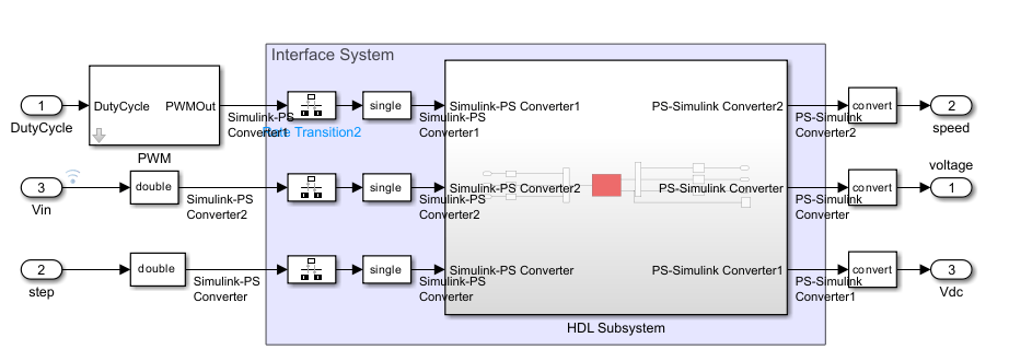
You generate VHDL® or Verilog® code for the blocks that are inside the green FPGA subsystem that contains the PWM generator and buck converter.
open_system('ee_buck_converter_dc_motor_hdl/FPGA')

In the model, the Buck Converter block represents a converter that steps down DC voltage as driven by an attached controller and gate-signal generator. Buck converters are also known as step-down voltage regulators because they decrease voltage magnitude. The Rotational Electromechanical Converter block provides an interface between the electrical and mechanical rotational domains. It converts electrical energy into mechanical energy in the form of rotational motion, and can also convert the rotational motion into electrical energy.
Run Desktop Simulation of Buck Converter Model
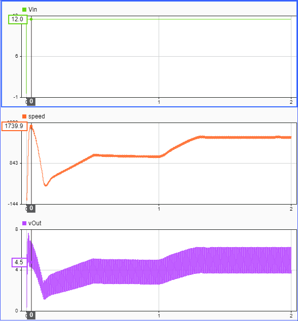
The input signals that include the DC input voltage, PWM frequency, and duty cycle are generated on the top level of the model. The sample time for the Simscape model is set to 6 μs. Signal logging is enabled on the top level of the model.
sim('ee_buck_converter_dc_motor_hdl')

% Display the buck converter output signals in SDI
Simulink.sdi.clearAllSubPlots
Simulink.sdi.setSubPlotLayout(3,1);

allIDs2 = Simulink.sdi.getAllRunIDs;
runID2 = allIDs2(end);
run2 = Simulink.sdi.getRun(runID2);
run2.name = 'Simscape Desktop Simulation';

run2.getAllSignals;
plotOnSubPlot(run2.getSignalsByName('Vin'),1,1,true);
plotOnSubPlot(run2.getSignalsByName('speed'),2,1,true);
plotOnSubPlot(run2.getSignalsByName('vOut'),3,1,true);

Simulink.sdi.view;
Generate HDL Implementation Model and Validate HDL Algorithm
The Simscape HDL Workflow Advisor converts the Simscape model to an HDL-compatible implementation model from which you generate HDL code. To open the Advisor, run the sschdladvisor function for your model.
sschdladvisor('ee_buck_converter_dc_motor_hdl')
To generate the HDL implementation model, in the Implementation model generation task drop-down list, right-click the Generate implementation model task, and then select Run to Selected Task from the list. After the task passes, you see a link to the HDL implementation model gmStateSpaceHDL_ee_buck_converter_dc_motor_.
open_system('gmStateSpaceHDL_ee_buck_converter_dc_motor_/FPGA')
To verify that the HDL implementation model matches the original Simscape model, generate a state-space validation model. In the Generate implementation model task, select the Generate validation logic for the implementation model check box and set the Validation logic tolerance to 1e-1. Then, run the task. See Validate HDL Implementation Model to Simscape Algorithm.
HDL Workflow Advisor
The HDL Workflow Advisor guides you through HDL code generation and the FPGA design process. Use the Advisor to:
Check the model for HDL code generation compatibility and fix incompatible settings.
hdlsetup('gmStateSpaceHDL_ee_buck_converter_dc_motor_')
Generate HDL code, test bench, and scripts to build and run the code and test bench.
Perform synthesis and timing analysis.
Deploy the generated code on SoCs, FPGAs, and Speedgoat I/O modules.
Generate FPGA Bitstream for Speedgoat Target Computer
Use HDL Workflow Advisor to Generate Simulink Real-Time Interface Model
1. Open the HDL implementation model, and then open the HDL Workflow Advisor for the implementation model.
open_system('gmStateSpaceHDL_ee_buck_converter_dc_motor_')
To open the HDL Workflow Advisor for a subsystem inside the model, use the hdladvisor function.
hdladvisor('gmStateSpaceHDL_ee_buck_converter_dc_motor_/FPGA')
2. In the Set Target Device and Synthesis Tool task, specify Target workflow as Simulink Real-Time FPGA I/O and Target platform as Speedgoat IO334-325K.

3. In the Set Target Reference Design task, select a value of X4 for the parameter PCIe lanes, and click the Run This Task button.

4. In Set Target Interface task, map the input and output single data type ports to PCIe Interface and click the Run This Task button.

5. In the Set Target Frequency task, the default value of Target Frequency (MHz) is set to 100. For this example model, this value is 164.

6. Right-click the Generate Simulink Real-Time Interface task, and select Run to Selected Task to generate the HDL IP core and FPGA bitstream.
Run Workflow Script to Generate Simulink Real-Time Interface Model
You can export the HDL Workflow Advisor settings to a script to expedite and automate your workflow. The script is a MATLAB® file that you run from the command line. You can modify and run the script, or import the settings into the HDL Workflow Advisor User Interface. See Run HDL Workflow with a Script.
This example shows how to run the HDL Workflow script. To generate a Simulink Real-Time Interface model, open and run this MATLAB script.
edit('hdlworkflow_dcmotor_IO334')
%--------------------------------------------------------------------------
% HDL Workflow Script
% This script contains the model, target settings, interface mapping, and
% the Workflow Configuration settings for generating HDL code for the HDL
% implementation model generated for the Buck Converter Model with DC Motor
% as load, and for deploying the code to the FPGA on board the Speedgoat
% IO334-325K module.
%--------------------------------------------------------------------------

%% Load the Model
load_system('gmStateSpaceHDL_ee_buck_converter_dc_motor_');

%% Model HDL Parameters
%% Set Model 'gmStateSpaceHDL_ee_buck_converter_dc_motor_' HDL parameters
hdlset_param('gmStateSpaceHDL_ee_buck_converter_dc_motor_', 'AdaptivePipelining', 'on');
hdlset_param('gmStateSpaceHDL_ee_buck_converter_dc_motor_', 'FPToleranceValue', 1.0e-01);
hdlset_param('gmStateSpaceHDL_ee_buck_converter_dc_motor_', 'FloatingPointTargetConfiguration', hdlcoder.createFloatingPointTargetConfig('NativeFloatingPoint' ...
, 'LatencyStrategy', 'Max') ...
);
hdlset_param('gmStateSpaceHDL_ee_buck_converter_dc_motor_', 'HDLSubsystem', 'gmStateSpaceHDL_ee_buck_converter_dc_motor_/FPGA');
hdlset_param('gmStateSpaceHDL_ee_buck_converter_dc_motor_', 'MaskParameterAsGeneric', 'on');
hdlset_param('gmStateSpaceHDL_ee_buck_converter_dc_motor_', 'Oversampling', 328);
hdlset_param('gmStateSpaceHDL_ee_buck_converter_dc_motor_', 'ReferenceDesign', 'Speedgoat IO334-325k');
hdlset_param('gmStateSpaceHDL_ee_buck_converter_dc_motor_', 'SynthesisTool', 'Xilinx Vivado');
hdlset_param('gmStateSpaceHDL_ee_buck_converter_dc_motor_', 'SynthesisToolChipFamily', 'Kintex7');
hdlset_param('gmStateSpaceHDL_ee_buck_converter_dc_motor_', 'SynthesisToolDeviceName', 'xc7k325t');
hdlset_param('gmStateSpaceHDL_ee_buck_converter_dc_motor_', 'SynthesisToolPackageName', 'fbg676');
hdlset_param('gmStateSpaceHDL_ee_buck_converter_dc_motor_', 'SynthesisToolSpeedValue', '-2');
hdlset_param('gmStateSpaceHDL_ee_buck_converter_dc_motor_', 'TargetDirectory', 'C:\BuckConverterDCMotor\hdl_prj\hdlsrc');
hdlset_param('gmStateSpaceHDL_ee_buck_converter_dc_motor_', 'TargetFrequency', 164);
hdlset_param('gmStateSpaceHDL_ee_buck_converter_dc_motor_', 'TargetPlatform', 'Speedgoat IO334-325k');
hdlset_param('gmStateSpaceHDL_ee_buck_converter_dc_motor_', 'Workflow', 'Simulink Real-Time FPGA I/O');

% Set SubSystem HDL parameters
hdlset_param('gmStateSpaceHDL_ee_buck_converter_dc_motor_/FPGA', 'AXI4SlaveIDWidth', '14');
hdlset_param('gmStateSpaceHDL_ee_buck_converter_dc_motor_/FPGA', 'ProcessorFPGASynchronization', 'Free running');

% Set Inport HDL parameters
hdlset_param('gmStateSpaceHDL_ee_buck_converter_dc_motor_/FPGA/DutyCycle', 'IOInterface', 'PCIe Interface');
hdlset_param('gmStateSpaceHDL_ee_buck_converter_dc_motor_/FPGA/DutyCycle', 'IOInterfaceMapping', 'x"100"');

% Set Inport HDL parameters
hdlset_param('gmStateSpaceHDL_ee_buck_converter_dc_motor_/FPGA/step', 'IOInterface', 'PCIe Interface');
hdlset_param('gmStateSpaceHDL_ee_buck_converter_dc_motor_/FPGA/step', 'IOInterfaceMapping', 'x"104"');

% Set Inport HDL parameters
hdlset_param('gmStateSpaceHDL_ee_buck_converter_dc_motor_/FPGA/Vin', 'IOInterface', 'PCIe Interface');
hdlset_param('gmStateSpaceHDL_ee_buck_converter_dc_motor_/FPGA/Vin', 'IOInterfaceMapping', 'x"108"');

% Set Outport HDL parameters
hdlset_param('gmStateSpaceHDL_ee_buck_converter_dc_motor_/FPGA/voltage', 'IOInterface', 'PCIe Interface');
hdlset_param('gmStateSpaceHDL_ee_buck_converter_dc_motor_/FPGA/voltage', 'IOInterfaceMapping', 'x"10C"');

% Set Outport HDL parameters
hdlset_param('gmStateSpaceHDL_ee_buck_converter_dc_motor_/FPGA/speed', 'IOInterface', 'PCIe Interface');
hdlset_param('gmStateSpaceHDL_ee_buck_converter_dc_motor_/FPGA/speed', 'IOInterfaceMapping', 'x"110"');

% Set Outport HDL parameters
hdlset_param('gmStateSpaceHDL_ee_buck_converter_dc_motor_/FPGA/Vdc', 'IOInterface', 'PCIe Interface');
hdlset_param('gmStateSpaceHDL_ee_buck_converter_dc_motor_/FPGA/Vdc', 'IOInterfaceMapping', 'x"114"');


%% Workflow Configuration Settings
% Construct the Workflow Configuration Object with default settings
hWC = hdlcoder.WorkflowConfig('SynthesisTool','Xilinx Vivado','TargetWorkflow','Simulink Real-Time FPGA I/O');

% Specify the top level project directory
hWC.ProjectFolder = 'C:\BuckConverterDCMotor\hdl_prj';
hWC.ReferenceDesignToolVersion = '2020.2';
hWC.IgnoreToolVersionMismatch = false;

% Set Workflow tasks to run
hWC.RunTaskGenerateRTLCodeAndIPCore = true;
hWC.RunTaskCreateProject = true;
hWC.RunTaskBuildFPGABitstream = true;
hWC.RunTaskGenerateSimulinkRealTimeInterface = true;

% Set properties related to 'RunTaskGenerateRTLCodeAndIPCore' Task
hWC.GenerateIPCoreReport = true;

% Set properties related to 'RunTaskCreateProject' Task
hWC.Objective = hdlcoder.Objective.None;
hWC.AdditionalProjectCreationTclFiles = '';
hWC.EnableIPCaching = true;

% Set properties related to 'RunTaskBuildFPGABitstream' Task
hWC.RunExternalBuild = false;
hWC.EnableDesignCheckpoint = false;
hWC.TclFileForSynthesisBuild = hdlcoder.BuildOption.Default;
hWC.CustomBuildTclFile = '';
hWC.DefaultCheckpointFile = 'Default';
hWC.RoutedDesignCheckpointFilePath = '';
hWC.MaxNumOfCoresForBuild = '';

% Validate the Workflow Configuration Object
hWC.validate;

%% Run the workflow
hdlcoder.runWorkflow('gmStateSpaceHDL_ee_buck_converter_dc_motor_/FPGA', hWC);
Deploy Bitstream to Speedgoat IO334-325k Target
Prepare Simulink Real-Time Interface Model for Real-Time Simulation
Running the workflow script generates RTL code and IP core, creates a Vivado project, builds the FPGA bitstream, and then generates the Simulink Real-Time interface model.
The FPGA subsystem is automatically replaced in the real-time interface model with Speedgoat driver blocks to initialize the hardware and to interface with the FPGA during runtime.

Make sure you comment out any remaining Rate Transition blocks in the model to obtain a single rate model. All the blocks in the generated Simulink Real-Time model are executed on the CPU of the real-time system. The buck converter and DC motor are programmed in the bitstream and run at the faster rate on the FPGA.
Connect to Target Machine and Run Real-Time Simulation
The model can now be deployed onto the Speedgoat real-time target machine. Make sure that the Speedgoat real-time target machine is connected to the host computer and powered on.
You download the bitstream by using the Simulink Real-Time Explorer. To open the Simulink Real-Time Explorer, enter the command slrtExplorer. Alternatively, you can open the Explorer from the Real-Time tab of the Simulink Toolstrip.
slrtExplorer
The Simulink Editor displays the Real-Time tab for models that are configured for the speedgoat.tlc code generation target. Click the Connect to Target Computer button in the Simulink Real-Time tab to connect to the machine. Once connected, click the Run on Target button to deploy the model.
Simulink Real-Time automatically generates C code from your model by using Simulink Coder. The generated code and the bitstream for the FPGA are loaded onto the target machine, and model execution starts automatically.
See Also
Functions
Topics
- Generate and Validate HDL Code for Simscape Model
- Simscape HDL Workflow Advisor Tasks
- FPGA-Based HIL Deployment of Simscape Model on Speedgoat FPGA I/O Module
- Deploy Simscape Grid Tied Converter Model to Speedgoat IO Module Using HDL Workflow Script
- Generate HDL Code for Nonlinear Simscape Models by Using Partitioning Solver