Author Audio System Reference Design for Basic Intel Evaluation Board
This example shows how to build a reference design to run an audio algorithm and access audio input and output on an Intel® Arrrow® SoC board.
Introduction
In this example, you create a reference design which receives audio input from Intel Arrow SoC Development Kit, performs some processing on it and transmits the processed audio data out of Arrow SoC Development Kit. To perform audio processing on Arrow SoC, you need the following 2 protocols:
I2C to configure the SSM2603 audio codec chip on Arrow SoC.
I2S to stream the digitized audio data between the codec chip and Cyclone V FPGA.
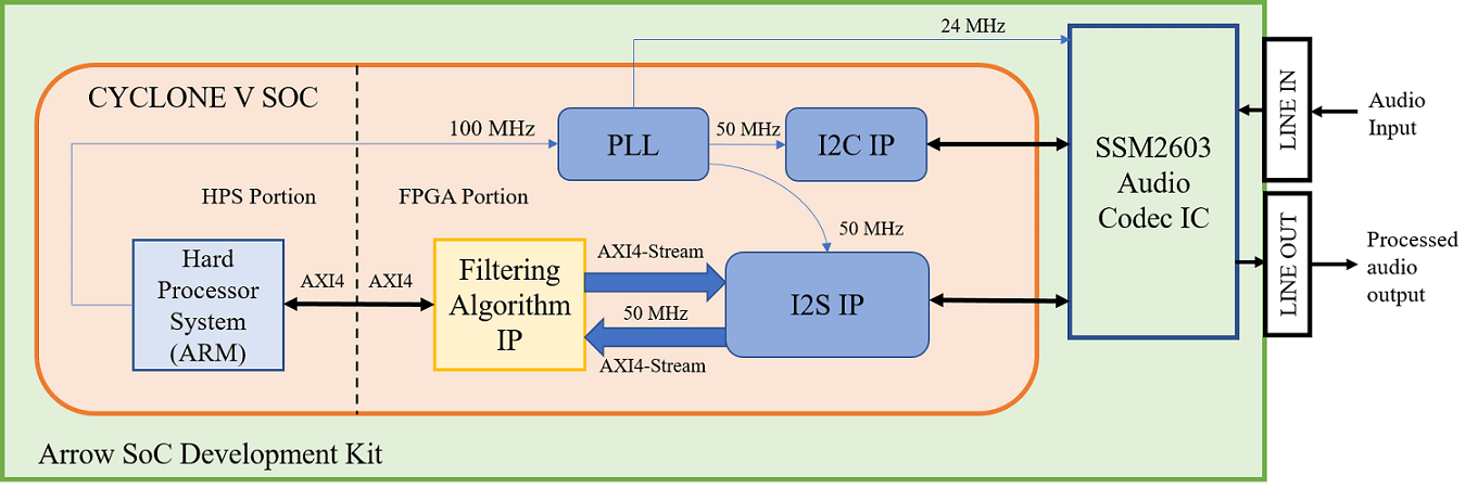
The above figure is a high level architecture diagram that shows how the reference design is used by the Filtering Algorithm IP. I2S IP operates at 50MHz frequency whereas one may want to run the Filtering Algorithm IP at a higher frequency. This frequency is controlled in Step 1.4 in HDL Workflow Advisor. In this example, assume that the filter operates at 50MHz. Depending on the type of filter selected, Filtering Algorithm IP filters a range of frequencies from the incoming audio data and passes the filtered audio data out. In the above figure, the Filtering Algorithm IP is our main algorithm that we are modeling in Simulink. While the I2C and I2S IPs need to be created. Here, you has 3 choices:
Use pre-packaged IP, e.g., if one exists
Model it in Simulink and generate an IP core using IP core generation workflow or
Use legacy HDL code. To create an IP out of legacy HDL code, use a Simulink model to black box the HDL code and generate IP core from it. I2C, I2S, PLL IPs and Cyclone V Hard Processor System(HPS) form a part of the reference design.
The following steps are used to create the reference design described above:
Generate IP Cores for peripheral interfaces
Create a custom audio codec reference design in Qsys
Create the reference design definition file
Verify the reference design
1. Generate IP Cores for peripheral interfaces using HDL Workflow Advisor
In this example,
I2C IP is developed by modeling it using Stateflow blocks, and also using legacy VHDL code for tristate buffer.
I2S IP is developed by modeling it in Simulink.
1.1 Creation of I2C IP
For creation of I2C IP to configure Audio Codec SSM2603, refer to Generate IP Core from I2C Controller Model Built Using Stateflow.
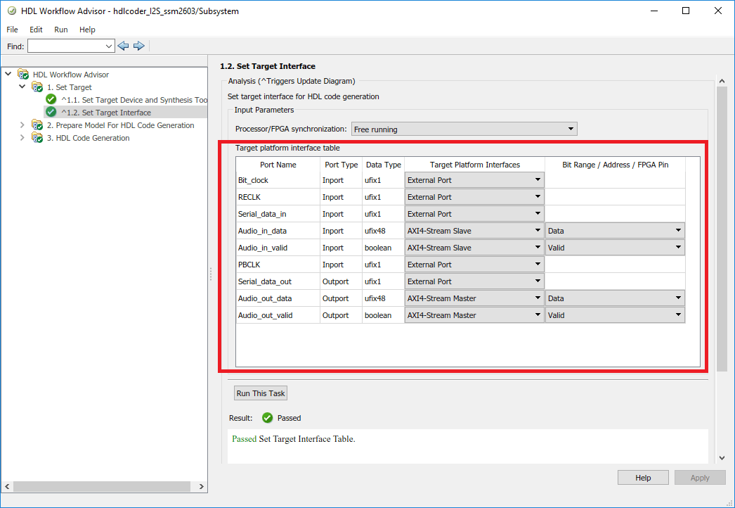
1.2 Creation of I2S IP
Design a model in Simulink with a MATLAB function which implements the I2S protocol.
modelname = 'hdlcoder_I2S_ssm2603';
open_system(modelname);
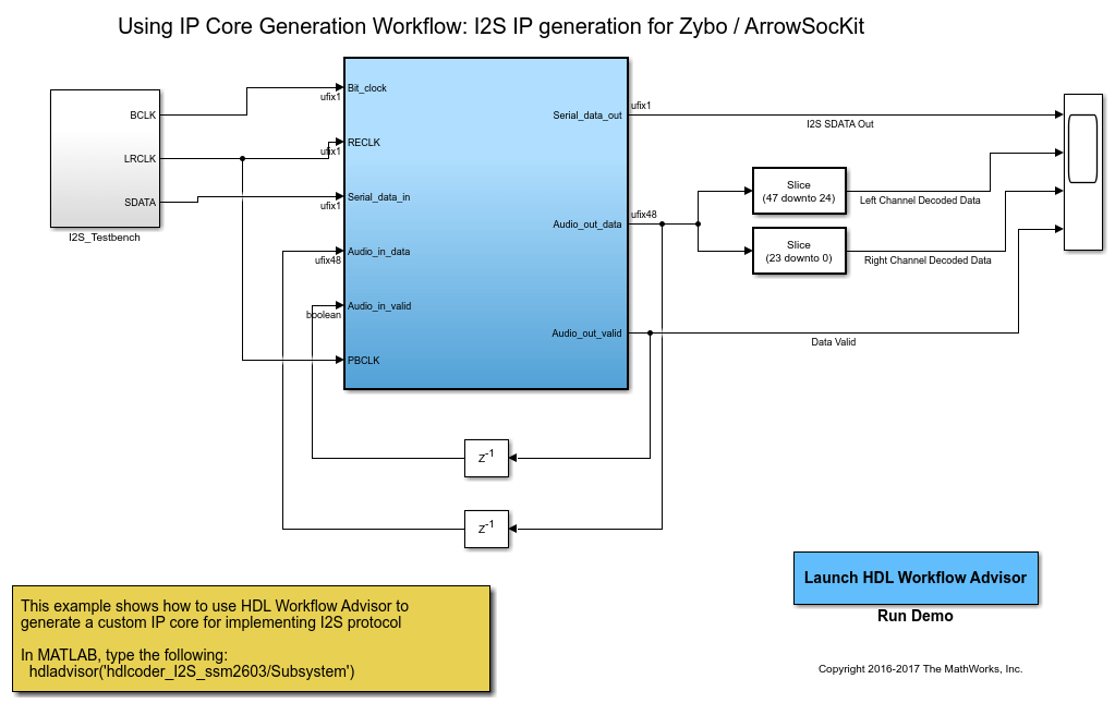
Create a test bench in the model to mimic the incoming audio data from the codec.
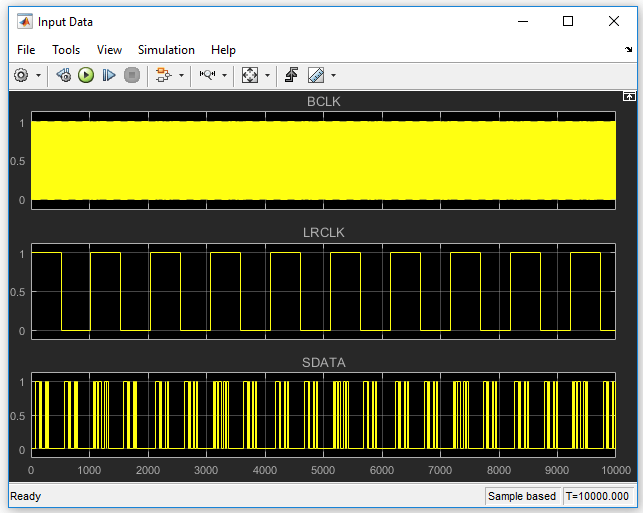
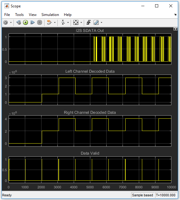
Feed this data to the Subsystem block which does the I2S operation. Verify the output of the Subsystem on a Scope.
Start the HDL Workflow Advisor from the DUT subsystem. In Task 1.1, keep the same settings as those of I2C IP generated earlier. in Task 1.2, set the Target Platform Interfaces as shown below:
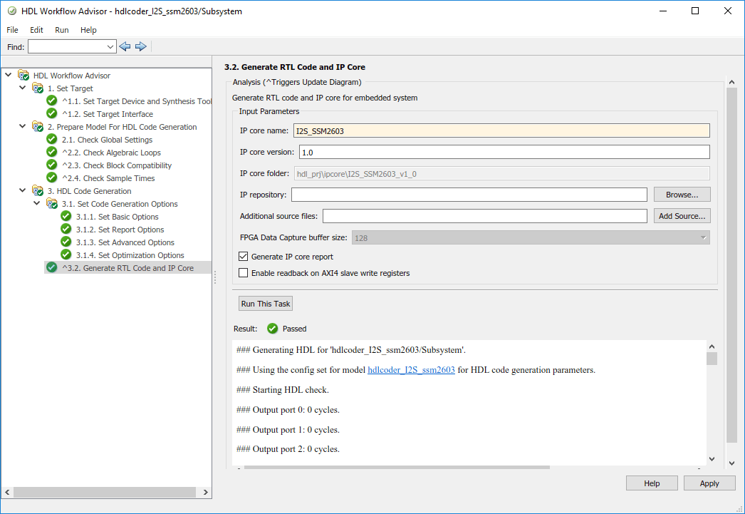
Run Task 3.2 and generate the ip core.
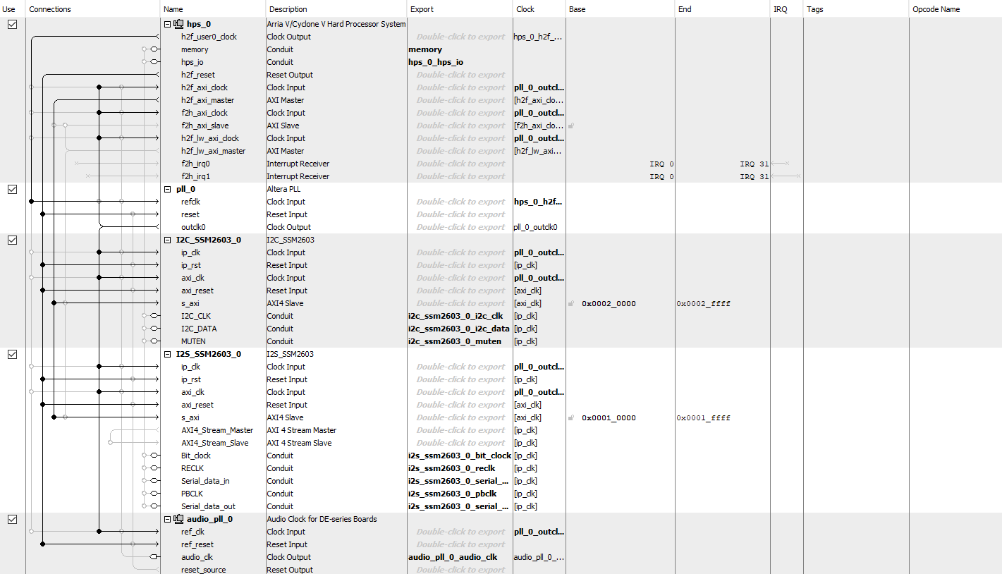
2. Create a custom audio codec reference design in Qsys
I2C and I2S IPs are incorporated in the custom reference design. To create a custom reference design, refer to the Reference Design creation using Intel Quartus Prime section in Define Custom Board and Reference Design for Intel Workflow.
Key points to be noted while creating this custom reference design:
We must understand the theory of operation of the audio codec chip on the Arrow SoC.
For the IP cores generated using HDL Workflow Advisor, IPCORE_CLK and AXI4_ACLK should be connected to the same clock source.
In this reference design, the audio codec is configured to operate in the Master mode.
The following signals run between the reference design on Intel SoC and the audio codec on Arrow SoC:
Bit_clock is the product of the sampling frequency, the number of bits per channel and the number of channels. It is driven by the audio codec in master mode. In this example, Sampling frequency is 48KHz, No of channels is 2, Number of bits per channel is 24.
Left_right_select is to distinguish between left audio channel data and right audio channel data. It is in sync with the Bit clock.
Serial_data_in is the analog to digital converted audio data from the codec.
Serial_data_out is the digital audio data going to codec to be converted into analog form.
I2C_CLK and I2C_DATA are standard I2C signals
ADDR0 and ADDR1 are the I2C Address Bits.
Clk_24MHz is the 24MHz clock signal required by the codec.
The custom audio codec reference design created for this example is shown below:
3. Create the reference design definition file
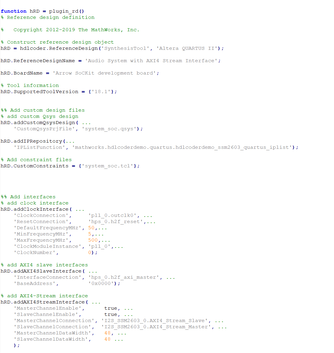
The following code describes the contents of the Arrow SoC Development Kit reference design definition file plugin_rd.m for the above reference design. For more details on how to define and register custom board, refer to Define Custom Board and Reference Design for Intel Workflow.
Add to MATLAB path the ArrowSoC folder using the following commands:
example_root = (hdlcoder_intel_examples_root)
cd (example_root)
addpath(genpath('ArrowSoC'));
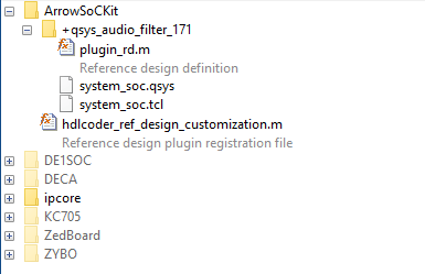
All files that are required for the reference design such as IP core files, qsys file, tcl file, plugin_rd file etc should be added to the MATLAB path, inside ArrowSoC folder using the hierarchy shown below. The user generated IP core files should be in +quartus folder. plugin_rd.m, tcl files and qsys files should be in the reference design plugin folder, for example, +qsys_audio_filter_18_1 folder.
4. Verify the reference design
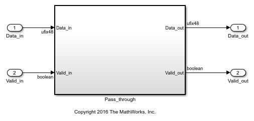
In order to ensure that the reference design and the interfaces in the reference design work as expected, design a Simulink model which just sends the audio through the Algorithm IP, integrate it with the reference design and test it on Arrow SoC. You should be able to hear the audio loop back.
modelname = 'hdlcoder_audio_pass_through';
open_system(modelname);
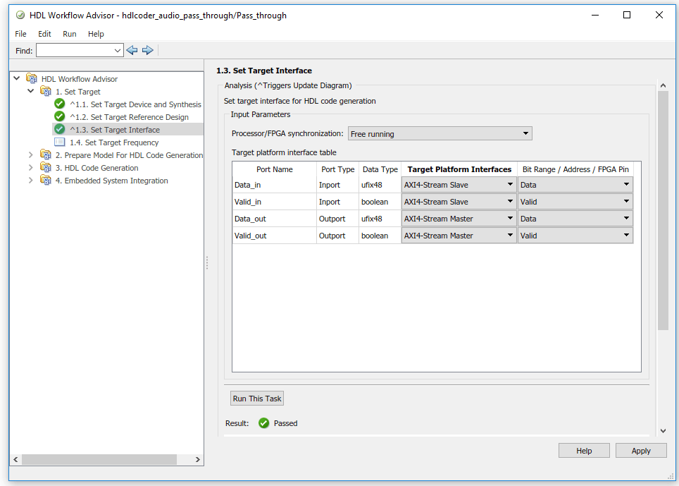
The interfaces in the model should be selected as shown below:
To generate IP core from a model and integrate it with the audio codec reference design, refer to Implement an Audio Filter on an Intel Board.