Add Comments to Generated HDL Code
R2026bAdding comments to generated HDL code improves traceability between your Simulink® model and the generated code. This traceability helps you verify design intent, meet compliance requirements, and simplify code reviews.
You can use these methods to add comments to generated HDL code:
| Method | Description |
|---|---|
| Simulink Annotations | Add free-form text comments to generated code by using model annotations. |
| Signal Descriptions | Add comments to signals by using the Description field. |
| Text Comments | Add plain-text comments by using DocBlock blocks. |
| Requirement Comments and Hyperlinks | Add comments or hyperlinked comments by using requirements links (requires Requirements Toolbox™). |
Simulink Annotations
You can add comments to blocks in the generated HDL code by using Simulink annotations. When you generate code from a model that contains Simulink annotations, HDL Coder™ renders the annotation text as plain-text comments in generated code. The comments appear at the same level of the model hierarchy as the subsystem that contains the annotations. For more information about annotations, see Annotate Models.
To add comments to a Constant block by using annotations, you must set these parameters in the Configuration Parameters window:
In the HDL Code Generation > Global Settings pane, in the Coding style tab, clear the Minimize intermediate signals check box.
In the HDL Code Generation > Report pane, set Traceability style to
Comment
                                Based
.
This image shows a model that has Simulink annotations for Inport blocks, Outport blocks, and other blocks.
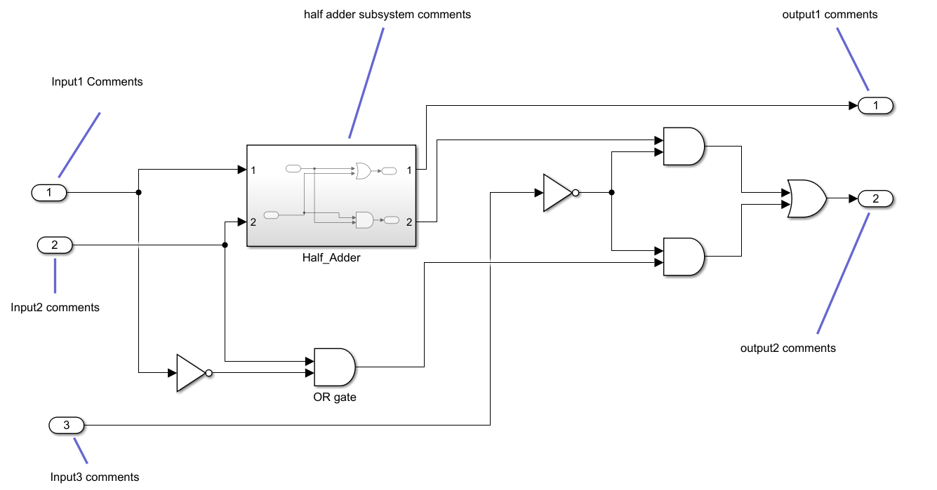
This generated code snippet shows the generated VHDL® code, which includes text comments for the blocks.
ENTITY Sub_Circuit IS
  PORT( -- Input1 Comments
        In1                               :   IN    std_logic;
        -- Input2 comments
        In2                               :   IN    std_logic;
        -- Input3 comments
        In3                               :   IN    std_logic;
        -- output1 comments
        Out1                              :   OUT   std_logic;
        -- output2 comments
        Out2                              :   OUT   std_logic
        );
END Sub_Circuit;
...
BEGIN
 -- half adder subsystem comments
  u_Half_Adder : Half_Adder
    PORT MAP( In1 => In1,
              In2 => In2,
              Out1 => Half_Adder_out1,
              Out2 => Half_Adder_out2
              );
...
Signal Descriptions
To add comments to a signal in the generated code, add a description to the signal in Simulink. In the generated code, these descriptions appear as comments above the signal declaration statements.
For example, to add a signal description in the
hdlcoder_simple_up_counter model:
Open the model.
openExample("hdlcoder_simple_up_counter");Open the
HDL_DUTsubsystem and right-click the signal you want to annotate.Select Properties to open the Signal Properties dialog box.
Select the Documentation tab and enter a description for the signal in the Description box.
Generate HDL code. The signal description appears as a comment above the signal declaration.
  ...
  -- Counter output value after delay
  SIGNAL count_out                        : unsigned(7 DOWNTO 0);  -- uint8
  ...
Note
In the signal description, use only ASCII characters. Non-ASCII characters might interfere with downstream synthesis and lint tools.
In some cases, optimizations might prevent the generated code from translating all signal descriptions to HDL comments. The generated code might also create duplicate HDL comments for certain signal descriptions.
Text Comments
To add plain-text comments to the HDL code, use a DocBlock block. DocBlock block content appears in the generated code as plain-text comments at the same level of the model hierarchy as the subsystem that contains the block. For more information about the DocBlock block, see DocBlock.
For example, to add a plain-text comment to the
hdlcoder_simple_up_counter model:
Open the model.
openExample("hdlcoder_simple_up_counter");Open the
HDL_DUTsubsystem.Add a DocBlock block to the subsystem.
Double-click the DocBlock block and enter the comment text you want to include in the generated code.
Right-click the DocBlock block and select View Mask > Mask Parameters. Set the Document type parameter to
Text. You cannot generate HDL comments forHTMLorRTFdocument types.Generate HDL code. The text from the DocBlock block appears as a comment in the generated code.
  ...
  reg [7:0] Delay1_out1;  // uint8

  // Up counter with configurable threshold

  assign enb = clk_enable;
  ...
Requirement Comments and Hyperlinks
If you have Requirements Toolbox, you can add comments to requirements by linking the requirements to model elements. For example:
Open the model.
openExample("hdlcoder_simple_up_counter");Open the Requirements Editor (Requirements Toolbox) and create a new requirement set named
Delay_requirements.slreqx. For more information, see Author Requirements in MATLAB or Simulink (Requirements Toolbox).Create a requirement with these details:
Custom ID:
1Summary:
Requirement 1Description:
Sample text
                                        1
Create another requirement with these details:
Custom ID:
2Summary:
Requirement 2Description:
Sample text 2
Tip
You can create links without leaving the Simulink Editor by using the Requirements Perspective. For more information, see View and Link Requirements in Simulink (Requirements Toolbox).
Open the
HDL_DUTsubsystem.Right-click the Delay block named
Delay. To add the Requirements Viewer app options to the context menu, point to Select Apps and click Requirements Viewer. Then, in the Requirements Viewer section, select Outgoing Links Editor.Link the requirements. Click the New button. Set the Description to
Requirements
                            1
, set Document type toRequirements Toolbox, set Document toDelay_requirements.slreqx, and set Location (Type/Identifier) toRequirement 1.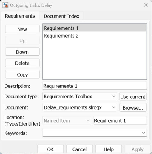
Repeat steps 5 and 6 to link
Requirement 2to the subsystem.Click Apply and OK.
Optionally, to add the code comments as hyperlinked comments, in the Configuration Parameters dialog box:
In the HDL Code Generation > Report pane, select Generate traceability report.
In the HDL Code Generation > Global Settings pane, in the Comments tab, select Include requirements in block comments.
Alternatively, set the
TraceabilityandRequirementCommentsproperties using themakehdlfunction.makehdl("hdlcoder_simple_up_counter/HDL_DUT",Traceability="on",RequirementComments="on");
Generate HDL code. The generated HDL code includes comments for the Delay block and
HDL_DUTsubsystem in thehdlcoder_simple_up_countermodel and contains links to the associated requirements for each block.// Module: HDL_DUT // Source Path: hdlcoder_simple_up_counter/HDL_DUT // Hierarchy Level: 0 // // Block requirements for HDL_DUT // 1. Requirement 2 // // ------------------------------------------------------------- ... // Block requirements for Delay1 // 1. Requirement 1 always @(posedge clk or posedge reset) begin : Delay1_process ... end ... endmodule // HDL_DUT

