ecompass
Orientation from magnetometer and accelerometer readings
Syntax
Description
The ecompass function computes the orientation of a
sensor using magnetometer and accelerometer readings to rotate quantities from a global
coordinate system to a body coordinate system.
orientation = ecompass(accelerometerReading,magnetometerReading)quaternion that
can rotate quantities from a parent (NED) frame to a child (sensor) frame.
orientation = ecompass(accelerometerReading,magnetometerReading,orientationFormat)quaternion or rotation
matrix.
orientation = ecompass(accelerometerReading,magnetometerReading,orientationFormat,'ReferenceFrame',RF)RF of the
orientation output.
Examples
Use the known magnetic field strength and proper acceleration of a device pointed true north in Boston to determine the magnetic declination of Boston.
Define the known acceleration and magnetic field strength in Boston.
magneticFieldStrength = [19.535 -5.109 47.930];
properAcceleration = [0 0 9.8];
Pass the magnetic field strength and acceleration to the ecompass function. The ecompass function returns a quaternion rotation operator. Convert the quaternion to Euler angles in degrees.
q = ecompass(properAcceleration,magneticFieldStrength);
e = eulerd(q,'ZYX','frame');
The angle, e, represents the angle between true north and magnetic north in Boston. By convention, magnetic declination is negative when magnetic north is west of true north. Negate the angle to determine the magnetic declination.
magneticDeclinationOfBoston = -e(1)
magneticDeclinationOfBoston =
-14.6563
The ecompass function fuses magnetometer and accelerometer data to return a quaternion that, when used within a quaternion rotation operator, can rotate quantities from a parent (NED) frame to a child frame. The ecompass function can also return rotation matrices that perform equivalent rotations as the quaternion operator.
Define a rotation that can take a parent frame pointing to magnetic north to a child frame pointing to geographic north. Define the rotation as both a quaternion and a rotation matrix. Then, convert the quaternion and rotation matrix to Euler angles in degrees for comparison.
Define the magnetic field strength in microteslas in Boston, MA, when pointed true north.
m = [19.535 -5.109 47.930];
a = [0 0 9.8];
Determine the quaternion and rotation matrix that is capable of rotating a frame from magnetic north to true north. Display the results for comparison.
q = ecompass(a,m);
quaterionEulerAngles = eulerd(q,'ZYX','frame')
quaterionEulerAngles = 1×3

   14.6563         0         0
r = ecompass(a,m,'rotmat');
theta = -asin(r(1,3));
psi = atan2(r(2,3)/cos(theta),r(3,3)/cos(theta));
rho = atan2(r(1,2)/cos(theta),r(1,1)/cos(theta));
rotmatEulerAngles = rad2deg([rho,theta,psi])
rotmatEulerAngles = 1×3
14.6563 0 0
Use ecompass to determine the gravity vector based on data from a rotating IMU.
Load the inertial measurement unit (IMU) data.
load 'rpy_9axis.mat' sensorData Fs
Determine the orientation of the sensor body relative to the local NED frame over time.
orientation = ecompass(sensorData.Acceleration,sensorData.MagneticField);
To estimate the gravity vector, first rotate the accelerometer readings from the sensor body frame to the NED frame using the orientation quaternion vector.
gravityVectors = rotatepoint(orientation,sensorData.Acceleration);
Determine the gravity vector as an average of the recovered gravity vectors over time.
gravityVectorEstimate = mean(gravityVectors,1)
gravityVectorEstimate = 1×3

    0.0000   -0.0000   10.2102
Fuse modeled accelerometer and gyroscope data to track a spinning platform using both idealized and realistic data.
Generate Ground-Truth Trajectory
Describe the ground-truth orientation of the platform over time. Use the kinematicTrajectory System object™ to create a trajectory for a platform that has no translation and spins about its z-axis.
duration = 12;
fs = 100;
numSamples = fs*duration;

accelerationBody = zeros(numSamples,3);

angularVelocityBody = zeros(numSamples,3);
zAxisAngularVelocity = [linspace(0,4*pi,4*fs),4*pi*ones(1,4*fs),linspace(4*pi,0,4*fs)]';
angularVelocityBody(:,3) = zAxisAngularVelocity;

trajectory = kinematicTrajectory('SampleRate',fs);

[~,orientationNED,~,accelerationNED,angularVelocityNED] = trajectory(accelerationBody,angularVelocityBody);
Model Receiving IMU Data
Use an imuSensor System object to mimic data received from an IMU that contains an ideal magnetometer and an ideal accelerometer.
IMU = imuSensor('accel-mag','SampleRate',fs);
[accelerometerData,magnetometerData] = IMU(accelerationNED, ...
                                           angularVelocityNED, ...
                                           orientationNED);
Fuse IMU Data to Estimate Orientation
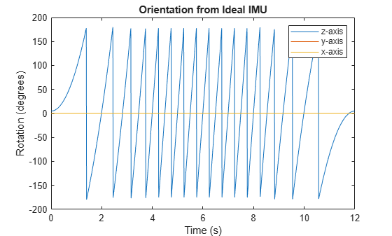
Pass the accelerometer data and magnetometer data to the ecompass function to estimate orientation over time. Convert the orientation to Euler angles in degrees and plot the result.
orientation = ecompass(accelerometerData,magnetometerData);
orientationEuler = eulerd(orientation,'ZYX','frame');

timeVector = (0:numSamples-1).'/fs;

figure(1)
plot(timeVector,orientationEuler)
legend('z-axis','y-axis','x-axis')
xlabel('Time (s)')
ylabel('Rotation (degrees)')
title('Orientation from Ideal IMU')
Repeat Experiment with Realistic IMU Sensor Model
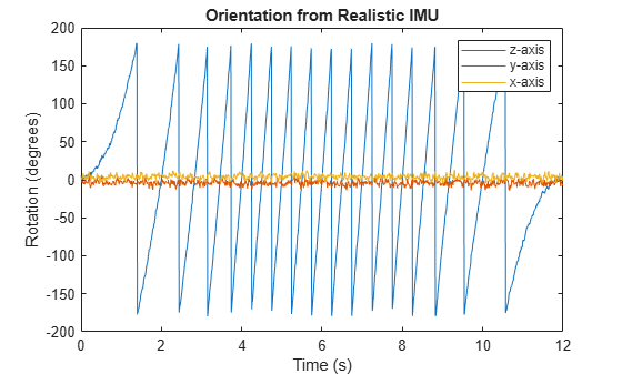
Modify parameters of the IMU System object to approximate realistic IMU sensor data. Reset the IMU and then call it with the same ground-truth acceleration, angular velocity, and orientation. Use ecompass to fuse the IMU data and plot the results.
IMU.Accelerometer = accelparams( ...
    'MeasurementRange',20, ...
    'Resolution',0.0006, ...
    'ConstantBias',0.5, ...
    'AxesMisalignment',2, ...
    'NoiseDensity',0.004, ...
    'BiasInstability',0.5);
IMU.Magnetometer = magparams( ...
    'MeasurementRange',200, ...
    'Resolution',0.01);
reset(IMU)

[accelerometerData,magnetometerData] = IMU(accelerationNED,angularVelocityNED,orientationNED);

orientation = ecompass(accelerometerData,magnetometerData);
orientationEuler = eulerd(orientation,'ZYX','frame');

figure(2)
plot(timeVector,orientationEuler)
legend('z-axis','y-axis','x-axis')
xlabel('Time (s)')
ylabel('Rotation (degrees)')
title('Orientation from Realistic IMU')
Input Arguments
Output Arguments
Algorithms
The ecompass function returns a quaternion or rotation matrix
that can rotate quantities from a parent (NED for example) frame to a child (sensor)
frame. For both output orientation formats, the rotation operator is determined by
computing the rotation matrix.
The rotation matrix is first calculated with an intermediary:
and then normalized column-wise. a and m are the
accelerometerReading input and the
magnetometerReading input, respectively.
To understand the rotation matrix calculation, consider an arbitrary point on the Earth and its corresponding local NED frame. Assume a sensor body frame, [x,y,z], with the same origin.

Recall that orientation of a sensor body is defined as the rotation operator (rotation matrix or quaternion) required to rotate a quantity from a parent (NED) frame to a child (sensor body) frame:
where
R is a 3-by-3 rotation matrix, which can be interpreted as the orientation of the child frame.
pparent is a 3-by-1 vector in the parent frame.
pchild is a 3-by-1 vector in the child frame.
For a stable sensor body, an accelerometer returns the acceleration due to gravity. If the sensor body is perfectly aligned with the NED coordinate system, all acceleration due to gravity is along the z-axis, and the accelerometer reads [0 0 1]. Consider the rotation matrix required to rotate a quantity from the NED coordinate system to a quantity indicated by the accelerometer.
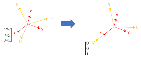
The third column of the rotation matrix corresponds to the accelerometer reading:
A magnetometer reading points toward magnetic north and is in the N-D plane. Again, consider a sensor body frame aligned with the NED coordinate system.
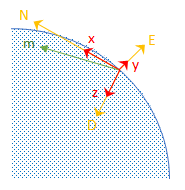
By definition, the E-axis is perpendicular to the N-D plane, therefore D ⨯ N = E, within some amplitude scaling. If the sensor body frame is aligned with NED, both the acceleration vector from the accelerometer and the magnetic field vector from the magnetometer lie in the N-D plane. Therefore a ⨯ m = y, again with some amplitude scaling.
Consider the rotation matrix required to rotate NED to the child frame, [x y z].
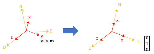
The second column of the rotation matrix corresponds to the cross product of the accelerometer reading and the magnetometer reading:
By definition of a rotation matrix, column 1 is the cross product of columns 2 and 3:
Finally, the rotation matrix is normalized column-wise:
Note
The ecompass algorithm uses magnetic north, not true north,
for the NED coordinate system.
References
[1] Open Source Sensor Fusion. https://github.com/memsindustrygroup/Open-Source-Sensor-Fusion/tree/master/docs
Extended Capabilities
Version History
Introduced in R2018b