이 페이지는 기계 번역을 사용하여 번역되었습니다. 최신 내용을 영문으로 보려면 여기를 클릭하십시오.
Switch
R2026a이 예제는 Simulink® 블록, Stateflow® 차트 및 MATLAB® 함수 블록을 사용하여 switch 구문을 구현하는 방법을 보여줍니다.
C 구조
switch (u1)
{
 case 2:
   y1 = u2;
   break;
 case 3:
   u3;
   break;
 default:
   y1 = u4;
   break;
}
스위치용 모델링 패턴: Switch Case 블록
switch 문을 생성하는 한 가지 방법은 Simulink > 신호 라우팅 라이브러리의 Switch Case 블록을 사용하는 것입니다.
1. 예제 모델 ex_switch_SL을 엽니다.
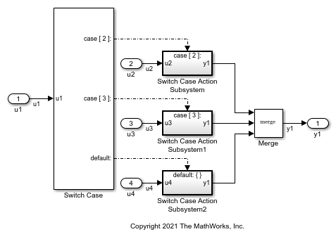
이 모델에는 Switch Case Action Subsystem가 포함되어 있습니다. Switch Case 블록은 정수형 입력을 받기 때문에, 입력 신호 u1는 int32로 형변환됩니다.
2. 모델을 구축하고 코드를 생성하려면 Ctrl+B를 누르십시오.
switch 구문을 구현하는 코드는 ex_switch_SL.c의 ex_switch_SL_step 함수에 있습니다:
/* Exported block signals */
int32_T u1;                            /* '<Root>/u1' */

/* External inputs (root inport signals with default storage) */
ExternalInputs rtU;

/* External outputs (root outports fed by signals with default storage) */
ExternalOutputs rtY;

/* Model step function */
void ex_switch_SL_step(void)
{
  /* SwitchCase: '<Root>/Switch Case' incorporates:
   *  Inport: '<Root>/u1'
   */
  switch (u1) {
   case 2:
    /* Outputs for IfAction SubSystem: '<Root>/Switch Case Action Subsystem' incorporates:
     *  ActionPort: '<S1>/Action Port'
     */
    /* Outport: '<Root>/y1' incorporates:
     *  Inport: '<Root>/u2'
     *  SignalConversion generated from: '<S1>/u2'
     */
    rtY.y1 = rtU.u2;

    /* End of Outputs for SubSystem: '<Root>/Switch Case Action Subsystem' */
    break;

   case 3:
    /* Outputs for IfAction SubSystem: '<Root>/Switch Case Action Subsystem1' incorporates:
     *  ActionPort: '<S2>/Action Port'
     */
    /* Outport: '<Root>/y1' incorporates:
     *  Inport: '<Root>/u3'
     *  SignalConversion generated from: '<S2>/u3'
     */
    rtY.y1 = rtU.u3;

    /* End of Outputs for SubSystem: '<Root>/Switch Case Action Subsystem1' */
    break;

   default:
    /* Outputs for IfAction SubSystem: '<Root>/Switch Case Action Subsystem2' incorporates:
     *  ActionPort: '<S3>/Action Port'
     */
    /* Outport: '<Root>/y1' incorporates:
     *  Inport: '<Root>/u4'
     *  SignalConversion generated from: '<S3>/u4'
     */
    rtY.y1 = rtU.u4;

    /* End of Outputs for SubSystem: '<Root>/Switch Case Action Subsystem2' */
    break;
  }

  /* End of SwitchCase: '<Root>/Switch Case' */
}

/* Model initialize function */
스위치용 모델링 패턴: MATLAB Function 블록
1. 예제 모델 ex_switch_ML을 엽니다.
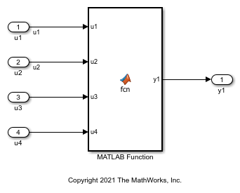
MATLAB 함수 블록에는 이 함수가 포함되어 있습니다:
function y1 = fcn(u1, u2, u3, u4)

switch u1
    case 2
        y1 = u2;
    case 3
        y1 = u3;
    otherwise
        y1 = u4;
end
2. 모델을 구축하고 코드를 생성하려면 Ctrl+B를 누르십시오.
switch 구문을 구현하는 코드는 ex_switch_ML.c의 ex_switch_ML_step 함수에 있습니다:
/* External inputs (root inport signals with default storage) */
ExternalInputs rtU;

/* External outputs (root outports fed by signals with default storage) */
ExternalOutputs rtY;

/* Model step function */
void ex_switch_ML_step(void)
{
  /* MATLAB Function: '<Root>/MATLAB Function' incorporates:
   *  Inport: '<Root>/u1'
   */
  switch (rtU.u1) {
   case 2:
    /* Outport: '<Root>/y1' incorporates:
     *  Inport: '<Root>/u2'
     */
    rtY.y1 = rtU.u2;
    break;

   case 3:
    /* Outport: '<Root>/y1' incorporates:
     *  Inport: '<Root>/u3'
     */
    rtY.y1 = rtU.u3;
    break;

   default:
    /* Outport: '<Root>/y1' incorporates:
     *  Inport: '<Root>/u4'
     */
    rtY.y1 = rtU.u4;
    break;
  }

  /* End of MATLAB Function: '<Root>/MATLAB Function' */
}

/* Model initialize function */
If-Elseif-Else 문구를 Switch 문으로 변환하기
MATLAB 함수 블록이나 Stateflow 차트가 if-elseif-else 결정 논리를 사용하는 경우, 구성 파라미터를 사용하여 해당 블록이나 차트를 switch 문으로 변환할 수 있습니다. 구성 파라미터 > 코드 생성 > 코드 스타일 > if-elseif-else 패턴을 switch-case 문으로 변환 파라미터를 선택하십시오. 자세한 내용은 Converting If-Elseif-Else Code to Switch-Case Statements 항목을 참조하십시오. Stateflow 차트를 사용한 이 변환에 대한 자세한 내용은 Enhance Readability of Code for Flow Charts를 참조하십시오.

