Estimate Orientation Using AHRS Filter and IMU Data on STM32 Processor Based Boards
This example shows how to stream inertial measurement unit (IMU) data from sensors connected to Nucleo-F302R8 board and estimate its orientation using an attitude and heading reference system (AHRS) filter.
Hardware Required
This example uses the following hardware:
NUCLEO-F302R8, an STM32 Nucleo-64 development board
X-NUCLEO-IKS01A2 sensor expansion board
The expansion board includes sensors that consist of an accelerometer, gyroscope, and magnetometer for tracking IMU data. The LSM6DSL sensor on the expansion board provides acceleration and angular rate values. The LSM303AGR sensor on the expansion board provides magnetic field values. You can read the sensor data using I2C protocol.
Hardware Connection
The sensor shield on the X-NUCLEO-IKS01A2 expansion board comes with NUCLEO-F302R8 connectors, which make it easy to interface the shield with the NUCLEO-F302R8 board. If you are using another type of STM32 board, connect the SDA, SCL, 3.3V, and GND pins of the STM32 board to the respective pins on the sensor shield.
Hardware Configuration
This example uses two Simulink models, AnalyseIMUData and EstimateOrientationUsingAHRSandIMU. Both models are preconfigured to work with the NUCLEO-F302R8 board. If you are using a different STM32 board, change the hardware board configuration in the AnalyseIMUData model by following these steps:
1. In the Simulink Toolstrip, on the Hardware tab, click Hardware Settings.
2. In the Configurations Parameters dialog box, select Hardware Implementation.
3. From the Hardware board list, select the STM32 board that you are using.
4. Click Apply. Click OK to close the dialog box.
Read and Calibrate Sensor Values
To read and analyze values, open the AnalyseIMUData model.

LSM6DSL Sensor
Embedded Coder Support Package for STM32 provides LSM6DSL IMU Sensor block to read acceleration and angular rate along the x-, y-, and z-axis from LSM6DSL sensor connected to the board. The block outputs acceleration in m/s2 and angular rate in rad/s. To further configure the sensor, you can click the block in the model.
LSM303AGR Sensor
To read magnetic field values from the LSM303AGR sensor, the model uses the I2C Controller Read and I2C Controller Write blocks from the support package.
These blocks use the I2C address or peripheral address of the LSM303AGR sensor, 0x1E, to configure and read the magnetic field value from the sensor.
The model initializes the sensor using the Initialize Function block. This one-time operation writes the output data rate (ODR) to the CFG_REG_A_M register (0x60) of the sensor. To see the available ODRs, refer to the LSM303AGR datasheet on the STMicroelectronics website.
The model reads the magnetic field from the output registers (0x68-0x6D) of the sensor using the I2C Controller Read block and converts the value to microtesla as required by the example.

Perform Magnetometer Calibration
To get accurate measurements from the LSM303AGR sensor, you must calibrate it. In this example, you calibrate the sensor to compensate for hard iron distortions. Hard iron effects are stationary interfering magnetic noise sources. Often, these distortions come from other metallic objects on the circuit board with the magnetometer. You can correct them by subtracting the correction value from the magnetometer readings for each axis.
To find the correction values:
1. In the AnalyseIMUData model use the To workspace block (out.MagneticField in the model) to log magnetometer data.
The model is preconfigured to run in Connected IO mode. This mode allows you to run your algorithm in Simulink with peripheral data from the hardware. For details, see Communicate with Hardware Using Connected IO.
2. Under the Hardware tab, with Connected IO mode selected, click Run with IO to simulate the model.

3. While the model is running, rotate the sensor from 0 to 360 degrees along each axis.
4. Click the Stop button to stop the simulation.
5. The model logs the magnetic field values in the MATLAB base workspace as an out.MagneticField variable. Use the magcal function in MATLAB command window to obtain the correction coefficients from the logged values.
[softIronFactor, hardIronOffset] = magcal(out.MagneticField);
The correction coefficients change with the surroundings.
Fuse Sensor Data with AHRS Filter
To fuse the sensor data with the AHRS filter and estimate the orientation, open the EstimateOrientationUsingAHRSandIMU model.
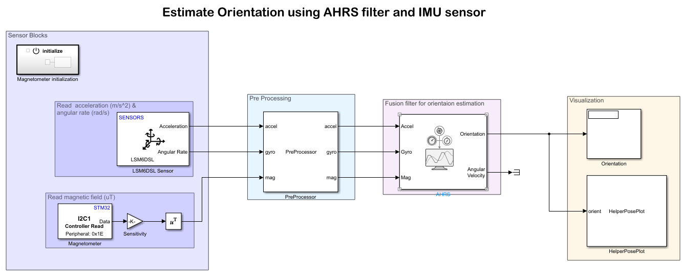
Sensor Blocks
The first part of this model reads the sensor values, as in the AnalyseIMUData model. If you make changes to sensor blocks in that model, make the corresponding changes in this model as well.
Preprocessor Block
The Preprocessor block in the model accepts acceleration, angular rate, and magnetic field from the sensor and magnetic field correction values. The block outputs the calibrated and axis-aligned sensor values.
Modify the values in the Constant block Magnetometer correction values, which is the input to the Preprocessor block, with the correction values (hardIronOffset) from calibrating the magnetometer.
The axes of the accelerometer, gyroscope, and magnetometer in the sensors might not be aligned with each other. Specify the index and sign of x-, y-, and z-axis of each sensor on the Preprocessor block mask so that each sensor aligns with the North-East-Down (NED) coordinate system when at rest. In this example, the magnetometer y-axes changes while the accelerometer and gyroscope axes remain fixed.
Filter Block
To estimate the orientation with IMU sensor data, this model uses an AHRS block. The AHRS block fuses accelerometer, magnetometer, and gyroscope sensor data to estimate device orientation. The AHRS block has tunable parameters. Tuning the parameters for the sensors that you are using can improve performance.
Visualization Block
To display the orientation in Simulink, this model provides a helper block, HelperPosePlot. The block plots the pose specified by the quaternion or rotation matrix.

Validate Model Design
To validate your design before generating the code and deploying it on the STM32 board, simulate the model in Connected IO mode. This mode of communication between the model and STM32 board does not require any code generation or model deployment, which accelerates the simulation process(see Communicate with Hardware Using Connected IO). The model is preconfigured to run in Connected IO mode.
This application requires the sensor data to be acquired in real-time. To get real time data with Connected IO mode, you must enable pacing. To acquire real-time data from the hardware:
1. In the Simulink Toolstrip, click the Simulation tab and set the simulation mode to Normal.
2. To run this model in Connected IO mode, click the Hardware tab, go to the Mode section, and select Connected IO.
3. On the Hardware tab, in the Run on Computer section, open the Run with IO list and select Simulation Pacing.
4. Select Enable pacing to slow down simulation.
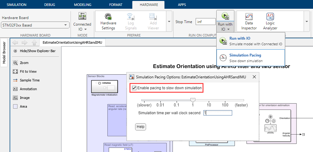
5. Click the Run icon for Run with IO to start the simulation.
Move the sensor and check if the motion in the figure matches the motion of the sensor.
6. To stop running the model, click the Stop icon for Run with IO.
Monitor and Tune Model Running on Hardware
After you successfully simulate the model in Connected IO mode, perform monitor and tune (external mode) action. The monitor and tune action deploys the model as C code on the hardware. The code obtains real-time data from the hardware. Using this mode, you can acquire data and tune parameters while the application runs on the hardware.
Notes:
Ensure that the STM32 board you are using has sufficient memory to run the application on hardware.
The HelperPosePlot block does not support monitor and tune action. To view the orientation in monitor and tune action, use other dashboards in Simulink such as Scope and Display blocks.
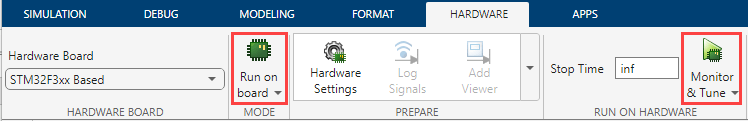
1. To perform monitor and tune action, click the Hardware tab, go to the Mode section, select Run on board (External mode) and then click Monitor & Tune.
The lower left corner of the model window displays status while Simulink prepares, downloads, and runs the model on the hardware.
Move the sensor and verify the orientation values.
2. To stop running the model, click Stop icon for Monitor and Tune.