Convert Sample and Frame Rates in Simulink Using Rate Conversion Blocks
Rate Conversion Blocks
There are two common types of operations that impact the frame and sample rates of a signal: direct rate conversion and frame rebuffering. Direct rate conversions such as upsampling and downsampling can be implemented by altering either the frame rate or the frame size of a signal. Frame rebuffering, which is used to alter the frame size of a signal in order to improve simulation throughput, usually also changes either the sample rate or the frame rate of the signal. For more details on the frame rebuffering technique, see Convert Sample and Frame Rates in Simulink Using Frame Rebuffering Blocks.
This topic contains two models that show how to change the sample rate of a signal using the direct rate conversion blocks. The following is a list of rate conversion blocks in DSP System Toolbox™ that are not based on filters.
Note that the upsampling and downsampling operations can introduce imaging and aliasing in the frequency domain, respectively. To prevent that from happening, use direct rate conversion blocks that are filter-based. For a list of the direct rate conversion blocks and the topics that show how to use these blocks, see Multirate and Multistage Filters.
Direct Rate Conversion Using the Rate options Parameter
In certain rate conversion blocks, the Rate options parameter determines whether the block operates in the single-rate mode or the multirate mode.
When Rate options parameter is set to:
Enforce single-rate processing: The block operates in the single-rate mode. The input and output sample rates of the block remain the same. However, the signal frame size changes according to the rate conversion factor specified in the block dialog box.Allow multirate processing: The block operates in the multirate mode. The input and output frame sizes of the block remain the same. However, the signal frame rate changes according to the rate conversion factor specified in the block dialog box.When a Simulink® model contains signals with various frame rates, the model is called multirate. For more information on multirate models, see Excess Algorithmic Delay (Tasking Latency). Also see Time-Based Scheduling and Code Generation (Simulink Coder).
The following two sections show how to change the sample rate of a signal using the two rate conversion modes in the Downsample block.
Rate Conversion by Frame-Rate Adjustment
Adjust the frame rate of the signal by setting the Rate options parameter of the rate conversion block to Allow multirate processing. In this mode, the sample rate of the signal changes by changing the frame rate of the signal while keeping the frame size constant.


where,
 is the output frame rate.
 is the input frame rate.
 is the output frame size.
 is the input frame size.
The sample rate of the output signal  is given by the following equation:
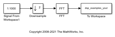
The 'ex_downsample_tut1' model shows rate conversion by frame-rate adjustment.
Open the model. In this model, the input signal is downsampled by a factor of 2 using the Downsample block. The Signal From Workspace block that generates the input signal has the Sample time parameter set to 0.125 seconds and the Samples per frame parameter set to 8. Therefore, the data generated by the block has a sample time of 0.125 seconds and a frame size of 8. The Input processing parameter in the Downsample block is set to Columns as channels (frame based), and the Rate options parameter is set to Allow multirate processing. This setting enables the Downsample block to operate in the multirate mode and treat data as frames of size 8.
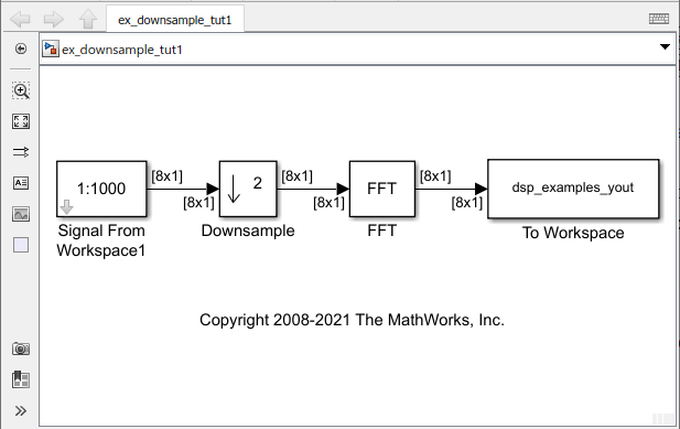
In the Debug tab, select Information Overlays > Signal Dimensions. When you run the model, the dimensions of the signals appear next to the lines connecting the blocks. The signal dimensions in the model confirm that the frame size of the signal remains the same between the input and output of the Downsample block.
To see the change in frame rate, enable sample time color coding by selecting Information Overlays > Colors.

Furthermore, to enable the annotation and Timing Legend, select Information Overlays > Text and Timing Legend. In the Timing Legend, you can view the value of the frame period for each signal in the model, the color associated with the frame period, and the corresponding annotation. For example, the frame period of the input signal (denoted by D1 in the Timing Legend) is given by  or
or  , which equals 1 second.
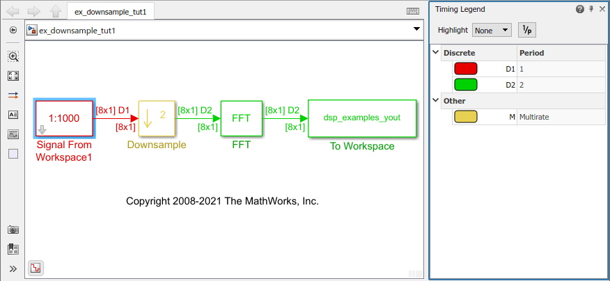
The Timing Legend in the model verifies that the output from the Downsample block has a frame period of 2 seconds, which is twice the frame period of the input . However, because the frame rate of the input  is 1 frame per second, and the frame rate of the output
  is 0.5 frames per second, the Downsample block actually downsampled the original signal to half its original rate. As a result, the output sample period,
  is doubled to 0.25 seconds without any change to the frame size.
Rate Conversion by Frame-Size Adjustment
Adjust the frame size of the signal by setting the Rate options parameter of the rate conversion block to Enforce single-rate processing. In this mode, the sample rate of the signal changes by changing the frame size of the signal while keeping the frame rate constant.


where,
 is the output frame size.
 is the input frame size.
 is the output frame rate.
 is the input frame rate.
The sample rate of the output signal  is given by the following equation:

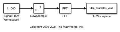
The 'ex_downsample_tut2' model shows rate conversion by frame-size adjustment.
Open the model. In this model, the input signal is downsampled by a factor of 2 using the Downsample block. The Signal From Workspace block that generates the input signal has the Sample time parameter set to 0.125 seconds, and the Samples per frame parameter is set to 8. Therefore, the data generated by the block has a sample time of 0.125 seconds and a frame size of 8. The Input processing parameter in the Downsample block is set to Columns as channels (frame based), and the Rate options parameter is set to Enforce single-rate processing. This setting enables the Downsample block to operate in the single-rate mode.
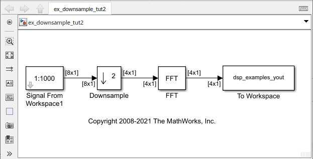
In the Debug tab, select Information Overlays > Signal Dimensions. When you run the model, the dimensions of the signals appear next to the lines connecting the blocks. The signal dimensions in the model confirm that the frame size of the signal decreases by a factor of 2 between the input and output of the Downsample block.
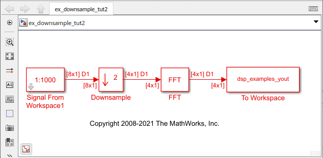
To see the effect on the frame rate, enable sample time color coding by selecting Information Overlays > Colors. You can see that all the blocks and signals are in the same color because they are operating at the same rate.
Furthermore, to enable the annotation and Timing Legend, select Information Overlays > Text and Timing Legend. In the Timing Legend, you can view the value of the frame period for each signal in the model, the color associated with the frame period, and the corresponding annotation. For example, the frame period of the input signal (denoted by D1 in the Timing Legend) is given by  or
or  , which equals 1 second. Therefore, the input frame rate
  is also 1 frame per second.
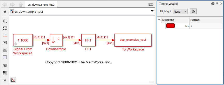
The Downsample block downsampled the input signal to half its original frame size. The signal dimensions of the output of the Downsample block confirm that the downsampled output has a frame size of 4, which is half the frame size of the input. As a result, the sample period of the output,  is 1/4 or 0.25 seconds. This process occurs without any change to the frame rate
  .
.