buildCalibrationBitstream
Class: dlhdl.ProcessorConfig
Namespace: dlhdl
Generate calibration bitstream to obtain double data rate (DDR) RAM response time
Since R2022b
Description
bitstreamPath = buildCalibrationBitstream(processorConfigObject)estimatePerformance method to
estimate the performance for a custom target board. Use the
deployCalibrationBitstream method to deploy the generated custom
bitstream.
Input Arguments
Output Arguments
Examples
This example shows how to create custom board and generate a deep learning processor IP core for the custom board. In this example you:
Create a custom board and reference design
Estimate the network performance and board resource utilization
Generate a custom processor and bitstream
Deploy the network by using the custom bitstream
The image shows the process of deploying a network to a custom board and retrieving a prediction from the deployed network.

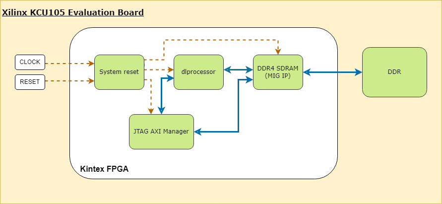
This example uses the Xilinx® Kintex® UltraScale™ KCU105 board. The board contains these blocks:
System reset block — Used to feed the clock and reset signals to the design.
Memory Interface Generator (MIG) IP block — Used to generate memory controllers and interfaces for Xilinx FPGAs.
MATLAB JTAG AXI Manager block — Used by MATLAB to access onboard memory location. For more details, see JTAG AXI Manager (HDL Verifier).
Integrate the generated deep learning processor IP core into your reference design. For more details, see Board and Reference Design Registration System (HDL Coder).
This image shows the generated deep learning processor IP core dl_processor0 integrated into the reference design.

This image shows system_0 block expanded, which contains the "MATLAB as AXI Master" block.
Once the block design is created, export it as a .tcl file.
Register Custom Board
Define the interface and attributes of a custom SoC board. To register the Xilinx® Kintex® UltraScale™ KCU105 board:
1. Create a board registration file with the name hdlcoder_board_customization.m and add it to the MATLAB path. The hdlcoder_board_customization.m function must return a second output. For more information, see Register a Custom Board (HDL Coder).
Set the target workflow to DeepLearningProcessor. For information on other target workflows supported by HDL Coder™, see Workflows in HDL Workflow Advisor (HDL Coder).
function [boardList, workflow] = hdlcoder_board_customization
  % Board plugin registration file
  % 1. Any registration file with this name on MATLAB path will be picked up
  % 2. Registration file returns a cell array pointing to the location of
  %    the board plugins
  % 3. Board plugin must be a package folder accessible from MATLAB path,
  %    and contains a board definition file
  %
  % Copyright 2022-2025 The MathWorks, Inc.
boardList = { ...
     'DLKCU105.plugin_board', ...
      };
workflow = hdlcoder.Workflow.DeepLearningProcessor;
end
2. Create the board definition file. To generate a deep learning processor, you must define the ExternalMemorySize. This property defines the memory size of the DDR on the target board.
% Copyright 2022-2025 The MathWorks, Inc.
% Board definition of KCU105
function hB = plugin_board()
% Construct board object
hB = hdlcoder.Board;
hB.BoardName = 'Xilinx Kintex-Ultrascale KCU105 evaluation board';
% FPGA device information
hB.FPGAVendor   = 'Xilinx';
hB.FPGAFamily   = 'KintexU';
hB.FPGADevice   = 'xcku040-ffva1156-2-e';
hB.FPGAPackage  = '';
hB.FPGASpeed    = '';
% Tool information
hB.SupportedTool = {'Xilinx Vivado'};
% FPGA JTAG chain position
hB.JTAGChainPosition = 1;
% Size of external DDR memory in bytes
hB.ExternalMemorySize = 0x80000000; % 2 GB
% Add interfaces
% Standard "External Port" interface
hB.addExternalPortInterface( ...
    'IOPadConstraint', {'IOSTANDARD = LVCMOS18'});
% Custom board external I/O interface
hB.addExternalIOInterface( ...
     'InterfaceID',    'LEDs General Purpose', ...
     'InterfaceType',  'OUT', ...
     'PortName',       'GPLEDs', ...
     'PortWidth',      8, ...
     'FPGAPin',        {'AP8', 'H23', 'P20', 'P21', 'N22', 'M22', 'R23','P23'}, ...
     'IOPadConstraint', {'IOSTANDARD = LVCMOS18'});
% Custom board external I/O interface
hB.addExternalIOInterface( ...
    'InterfaceID',    'User Push Buttons', ...
    'InterfaceType',  'IN', ...
    'PortName',       'PB', ...
    'PortWidth',      1, ...
    'FPGAPin',        {'AE10'}, ...
    'IOPadConstraint', {'IOSTANDARD = LVCMOS18'});
Register Custom Reference Design
Define the interface and attributes of a custom SoC reference design. To create a custom reference design:
1. Create a reference design registration file named hdlcoder_ref_design_customization.m that contains the list of reference design plugins associated with the board. For more information, see Register a Custom Reference Design (HDL Coder).
function [rd, boardName] = hdlcoder_ref_design_customization
% Reference design plugin registration file
% 1. The registration file with this name inside of a board plugin folder
%    will be picked up
% 2. Any registration file with this name on MATLAB path will also be picked up
% 3. The registration file returns a cell array pointing to the location of
%    the reference design plugins
% 4. The registration file also returns its associated board name
% 5. Reference design plugin must be a package folder accessible from
%    MATLAB path, and contains a reference design definition file
%
%   Copyright 2022-2025 The MathWorks, Inc.
rd = {'DLKCU105.ReferenceDesign.plugin_rd', ...
  };
boardName = 'Xilinx Kintex-Ultrascale KCU105 evaluation board';
end
2. Create the reference design definition file. To generate a deep learning processor IP core, you must define these three AXI4 Master Interfaces:
AXI4 Master Activation DataAXI4 Master Weight DataAXI4 Master Debug
function hRD = plugin_rd()
% Reference design definition
% Copyright 2022-2025 The MathWorks, Inc.
% Construct reference design object
hRD = hdlcoder.ReferenceDesign('SynthesisTool', 'Xilinx Vivado');
hRD.ReferenceDesignName = 'AXI-Stream DDR Memory Access : 3-AXIM';
hRD.BoardName = 'Xilinx Kintex-Ultrascale KCU105 evaluation board';
% Tool information
hRD.SupportedToolVersion = {'2022.1','2023.1','2024.1'};
% Add custom design files
% add custom Vivado design
hRD.addCustomVivadoDesign( ...
  'CustomBlockDesignTcl', 'system_top.tcl',...
  'VivadoBoardPart',      'xilinx.com:kcu105:part0:1.0');
% Add HDL Verifier JTAG as AXI Master IP from support package
hRD.addIPRepository( ...
  'IPListFunction','hdlverifier.fpga.vivado.iplist', ...
  'NotExistMessage', 'IP Repository not found.');
% Add interfaces
% add clock interface
hRD.addClockInterface( ...
     'ClockConnection',      'system_0/clk_out1', ...
     'ResetConnection',      'system_0/peripheral_aresetn',...
     'DefaultFrequencyMHz',  125,...
     'MinFrequencyMHz',      10,...
     'MaxFrequencyMHz',      250,...
     'ClockNumber',          1,...
     'ClockModuleInstance',  'system_0/clk_wiz_0');
% add Register interfaces
% This Register Interface such as AXI4 interface is used for interacting between DDR4 and Deep Learning IP
hRD.addRegisterInterface( ...
    'InterfaceConnection', 'system_0/M_AXI', ...
    'BaseAddress',         '0x44A00000',...
    'MasterAddressSpace',  'system_0/hdlverifier_axi_manager_0/axi4m',...
    'InterfaceType',       'AXI4');
% AXI4 Master Interface for the layer activation data with max data bit-width of 512
hRD.addAXI4MasterInterface(...
        'InterfaceID',         'AXI4 Master Activation Data', ...
        'ReadSupport',          true, ...
        'WriteSupport',         true, ...
        'MaxDataWidth',         512, ...
        'AddrWidth',            32, ...
        'InterfaceConnection', 'axi_interconnect_0/S01_AXI',...
        'TargetAddressSegments', {{'ddr4_0/C0_DDR4_MEMORY_MAP/C0_DDR4_ADDRESS_BLOCK',hex2dec('80000000'),hex2dec('80000000')}});
% AXI4 Master Interface for the layer weight data with max data bit-width of 512
hRD.addAXI4MasterInterface(...
        'InterfaceID',         'AXI4 Master Weight Data', ...
        'ReadSupport',          true, ...
        'WriteSupport',         true, ...
        'MaxDataWidth',         512, ...
        'AddrWidth',            32, ...
        'InterfaceConnection', 'axi_interconnect_0/S02_AXI',...
        'TargetAddressSegments', {{'ddr4_0/C0_DDR4_MEMORY_MAP/C0_DDR4_ADDRESS_BLOCK',hex2dec('80000000'),hex2dec('80000000')}});
% AXI4 Master Interface for the debugger with max data bit-width of 512
hRD.addAXI4MasterInterface(...
        'InterfaceID',         'AXI4 Master Debug', ...
        'ReadSupport',          true, ...
        'WriteSupport',         true, ...
        'MaxDataWidth',         512, ...
        'AddrWidth',            32, ...
        'InterfaceConnection', 'axi_interconnect_0/S03_AXI',...
        'TargetAddressSegments', {{'ddr4_0/C0_DDR4_MEMORY_MAP/C0_DDR4_ADDRESS_BLOCK',hex2dec('80000000'),hex2dec('80000000')}});
3. The reference design plugin file must contain information about the target interface and the deep learning processor IP core, the memory address space for the deep learning processor IP core, and a command to validate the reference design. The file also requires information on the resources consumed by the reference design. This information is used during resource estimation. Add the deep learning processor information to the reference design file:
% Deep learning specific properties
hRD.registerDeepLearningTargetInterface("JTAG");
hRD.registerDeepLearningMemoryAddressSpace(0x80000000, 0x80000000); % 2GB
% Resource utilization information
hRD.ResourcesUsed.LogicElements = 30500;
hRD.ResourcesUsed.DSP = 3;
hRD.ResourcesUsed.RAM = 26.5;
File Hierarchy
The files created need to be saved in the following hierarchy:
Performance Estimation
Reduce the time required to design and deploy a custom deep learning network that meets performance requirements by analyzing the layer-level latencies before deploying the network.
Estimate the performance of network for your custom board by collecting calibration data from the custom board, by:
Generating a calibration bitstream
Deploying the calibration bitstream to the target custom board
Retrieving the external to internal memory transaction latencies
Create a Processor Configuration object.
hPC = dlhdl.ProcessorConfig;
Specify the TargetPlatform. This automatically sets the SynthesisToolChipFamily, SynthesisToolDeviceName, and ReferenceDesign properties.
hPC.TargetPlatform = 'Xilinx Kintex-Ultrascale KCU105 evaluation board';
Set the target frequency.
hPC.TargetFrequency = 100;
This example uses a ResNet-18 pretrained network. For more details, see resnet18. Set the deep learning network:
net = imagePretrainedNetwork('resnet18');
To fit this design onto the target, reduce the number of parallel convolution processor kernel threads for the conv module to 9.
setModuleProperty(hPC, 'conv', 'ConvThreadNumber', 9);
Set the Xilinx Vivado toolpath to your design tool using the hdlsetuptoolpath function, then build the calibration bitstream.
hdlsetuptoolpath('ToolName','Xilinx Vivado','ToolPath','C:\Xilinx\Vivado\2024.1\bin\vivado.bat');
bitstreamPath = buildCalibrationBitstream(hPC);
Deploy the bitstream to the hardware and obtain the external- to-internal memory transaction latencies. You can use these values to get better estimates for the layer-level latencies.
deployCalibrationBitstream(hPC, bitstreamPath);
The deployCalibrationBitstream saves the calibration data from the hardware as a structure in the CalibrationData property of the dlhdl.ProcessorConfig object. The function also saves the calibration data as a MAT-file with the name calibrationData.mat. You can load this data into a new dlhdl.ProcessorConfig object by entering:
load('calibrationData.mat');
hPC.CalibrationData = calData;
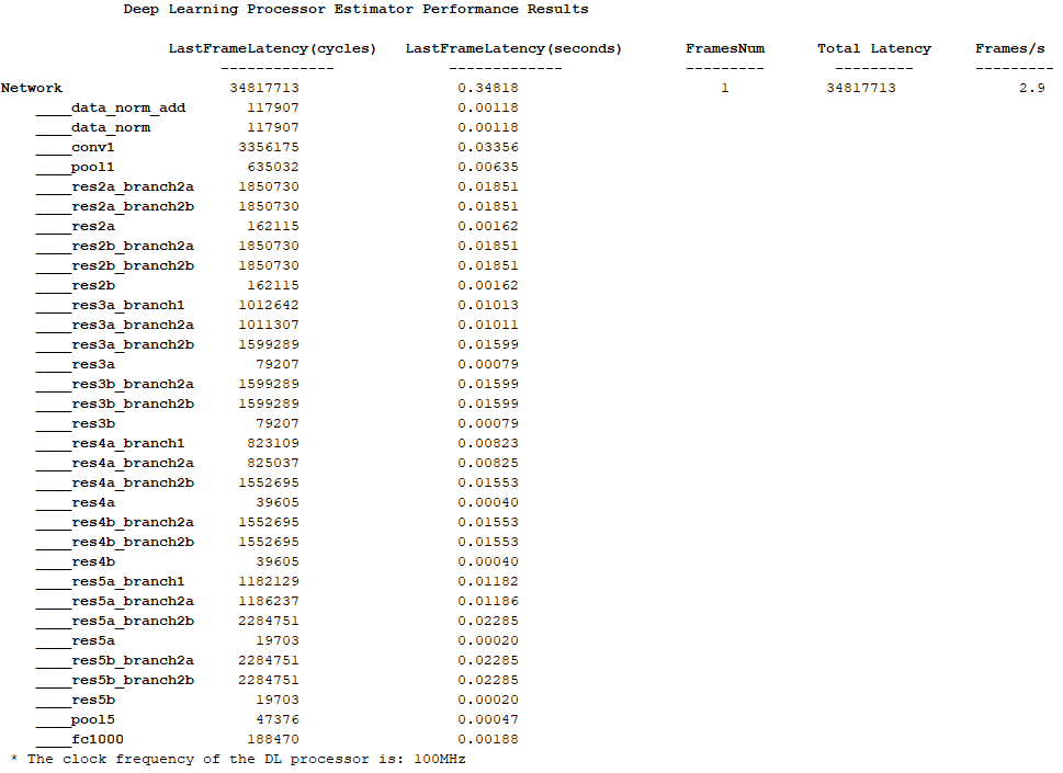
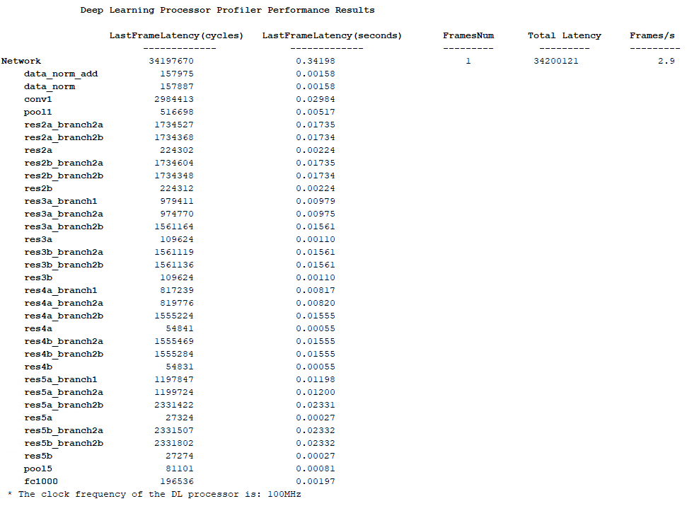
Estimate the performance of the network for the custom processor configuration.
estimatePerformance(hPC, net);
Resource Estimation
Verify that the generated bistream and network fit on your target custom board, by using estimateResources to estimate the resource utilization. To learn how to estimate the resource utilization for your custom boards, see Estimate Resource Utilization for Custom Board and Reference Design.
Generate Custom Bitstream for Custom Processor Configuration
Generate a bitstream for the custom processor configuration hPC.
dlhdl.buildProcessor(hPC);
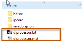
Locate the bitstream file and associated MAT file at cwd\dlhdl_prj\, where cwd is your current working folder. The name of the bitstream file is dlprocessor.bit. The name of the MAT file is dlprocessor.mat. To use the generated bitstream for the supported Xilinx boards, copy the dlprocessor.bit and dlprocessor.mat files to the current working folder.

Deploy the Custom Bitstream and Run Predictions on the Network
After you generate the bitstream, deploy the network and run the predictions on the network. For more information, refer to the Prototype Deep Learning Networks on FPGA and SoC Devices page. For an example on prototyping, see Bicyclist and Pedestrian Classification by Using FPGA.
Create Target Object
Create a target object with the vendor name of the target device. Specify the interface to connect the target device to the host using the Interface name-value pair. This example connects to the target using the JTAG interface.
hT = dlhdl.Target('Xilinx', 'Interface', 'JTAG')
Create Workflow Object for ResNet-18 Network
Create an object of the dlhdl.Workflow class. Specify the network, the bitstream name, and the target object.
hW = dlhdl.Workflow('Network', net, 'Bitstream', 'dlprocessor.bit', 'Target', hT);
Compile the Network
Run the compile function of the dlhdl.Workflow object.
compile(hW)
Deploy the Bitstream to the FPGA
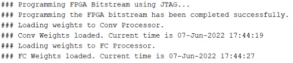
To deploy the network on the Xilinx KCU105 Kintex hardware, run the deploy function of the dlhdl.Workflow object.
deploy(hW)

Run Prediction for the Network
Load the sample image.
img = imread('sampleImage1.png');
imshow(img);

Run a prediction on the image. The result output argument contains the output of the layer preceding the ClassificationOutputLayer and speed contains the profiler table.
[result, speed] = predict(hW, img, 'Profile', 'on');
Get the output class from the prediction.
[value,idx] = max(result);
classNames = net.Layers(end).Classes;
classNames(idx)
Version History
Introduced in R2022b