Multistream Audio Simulation in a Bluetooth LE Piconet
This example shows how to create, configure, and simulate multistream audio in a Bluetooth® low energy (LE) piconet.
Using this example, you can:
Create and configure a Bluetooth LE piconet consisting of a source node and two sink nodes.
Establish asynchronous connection-oriented (ACL) and connected isochronous stream (CIS) connection between the source and sink nodes.
Add On-Off application traffic between the source and sink nodes.
Add a custom path loss model in the piconet.
Simulate the scenario and visualize the packet communication and state transitions of source and sink nodes over time.
Additionally, you can use this example script to perform these tasks.
Multistream Audio Simulation Scenario
Multistream audio enables you to transmit multiple, independent, and synchronized audio streams between an audio source device, such as a smartphone, and one or more audio sink devices like earbuds or hearing aids. To support multistream audio, the Bluetooth Core Specification 5.2 [2] introduced the CIS and CIG. For more information about multistream audio, see Bluetooth LE Audio. The example simulates this scenario.

The scenario consists of an audio source (Android TV) and two audio sinks (earbuds). The source sends distinct left and right audio streams to left sink and right sink, respectively. Initially, the source must establish ACL links with both the sink nodes. The control data for audio streaming is transmitted over the ACL links by using the connection events. The audio data is transmitted from the source to the right sink and left sink by using the respective CIS events. For more information about CIS events, see Bluetooth LE Audio.
Create and Configure LE Piconet
Set the seed for the random number generator to 1 to ensure repeatability of results. The seed value controls the pattern of random number generation. Initializing the random number generator using the same seed, assures the same result. To improve the accuracy of your simulation results after running the simulation, you can change the seed value, run the simulation again, and average the results over multiple simulations.
rng(1,"twister");Create a wireless network simulator object.
networkSimulator = wirelessNetworkSimulator.init;
Specify the simulation time in seconds.
simulationTime = 2;
Create a Bluetooth LE node, specifying the role as "central". Specify the name and position of the node. Additionally, you can also assign mobility to the Central and Peripheral nodes by using the addMobility object function of the bluetoothLENode object.
source = bluetoothLENode("central",Name="source");
source.Position = [0 0 0];                         % x-, y-, and z- coordinates in meters
Create two Bluetooth LE nodes, specifying the role as "peripheral". Specify the name and position of the nodes.
leftSink = bluetoothLENode("peripheral",Name="leftSink");
leftSink.Position = [7 0 0];                                % x-, y-, and z- coordinates in meters
rightSink = bluetoothLENode("peripheral",Name="rightSink");
rightSink.Position = [7.2 0 0];                             % x-, y-, and z- coordinates in meters
To set the timing of ACL and CIS events, specify these values.
Connection interval - This value specifies the time between the successive anchor points of the connection events.
Isochronous (ISO) interval - This value specifies the time between the successive anchor points of the CIS events.
To stream CIS events, the source must establish an ACL link with the left and right sink. The control data for audio streaming is transmitted over ACL logical transport by using the connection events. The audio data is transmitted by using the CIS logical transport through the CIS events.
isoInterval = 0.030;        % In seconds
connectionInterval = 0.060; % In seconds
Create a Bluetooth LE CIS configuration object, specifying the ISO interval and number of subevents.
cfgCIS = bluetoothLECISConfig(ISOInterval=isoInterval,NumSubevents=2);
Create a Bluetooth LE connection configuration object, specifying the connection interval and active period of ACL connection. The active period of the ACL connection impacts the active period of CIS event.
cfgConnection = bluetoothLEConnectionConfig(ConnectionInterval=connectionInterval,ActivePeriod=0.001,MaxPDU=27);
Configure the ACL and CIS connection between the source and the left sink. As the connection offset for the left sink is set to 0 seconds, the connection events for the left sink occur at the beginning of the simulation. The CIS events for the left sink occur at the end of its active period within the ACL connection. Subsequently, both ACL and CIS connection events occur at regular intervals.
cfgConnection.AccessAddress = "B6B3F161";
cfgConnection.ConnectionOffset = 0;                                                                                          % In seconds
[leftConnCfg,leftCISCfg] = configureConnection(cfgConnection,source,leftSink,CISConfig=cfgCIS);
Configure the ACL and CIS connection between the source and the right sink. The connection events for the right sink occur at the specified connection offset by using the start of the simulation as the reference point. The CIS events for the right sink occur at the end of the first CIS event of the left sink.
cfgConnection.AccessAddress = "63154C1D";
cfgConnection.ConnectionOffset = 0.030;                                                                                       % In seconds
[rightConnCfg,rightCISCfg] = configureConnection(cfgConnection,source,rightSink,CISConfig=cfgCIS);
Create a Bluetooth LE piconet consisting of source and sink nodes.
nodes = [source leftSink rightSink];
Visualize Wireless Network
To visualize the nodes in Bluetooth LE connected audio network, use the wirelessNetworkViewer object. The visualization shows the node placements in the Cartesian plane. To add the central and peripheral nodes to the wireless network viewer, use the addNodes object function of the wirelessNetworkViewer object.
viewerObj = wirelessNetworkViewer();
addNodes(viewerObj,source,Type="Source");
addNodes(viewerObj,[leftSink rightSink],Type="Sink");
Add Application Traffic
Create a networkTrafficOnOff (Wireless Network Toolbox) object to generate an On-Off application traffic pattern. Configure the On-Off application traffic pattern at the left sink and right sink by specifying the application data rate, packet size, and on state duration.
trafficSource = networkTrafficOnOff(DataRate=67,PacketSize=251,OnTime=Inf,OffTime=0);
Add application traffic between source and both the sinks by using the addTrafficSource object function.
addTrafficSource(source,trafficSource,DestinationNode=leftSink,CISConfig=leftCISCfg);
addTrafficSource(source,trafficSource,DestinationNode=rightSink,CISConfig=rightCISCfg);
Add Custom Path Loss Model
To add your own custom path loss model, enable the enableCustomPathloss flag. If you set this flag to false, the example uses free-space path loss model.
enableCustomPathloss =true; environment =
"Home";
Create a path loss model by using the bluetoothPathLossConfig object and bluetoothPathLoss function. The updatePathLoss function creates a path loss model function handle. Add the path loss model to the wireless network simulator by using the addChannelModel (Wireless Network Toolbox) object function. Note that this custom path loss model is applicable only for 2.4 GHz frequency band.
if enableCustomPathloss
    cfgPathloss = bluetoothPathLossConfig(Environment=environment);
    pathlossHandle = @(rxInfo,txData) updatePathLoss(rxInfo,txData,cfgPathloss); % Path loss function
    addChannelModel(networkSimulator,pathlossHandle);
end
Capture IQ Samples
To capture IQ samples for all the nodes in the simulation, enable the enableIQSampleCapture flag. The receiving node captures the IQ samples based on the relevant packets received.
enableIQSampleCapture =  false;
Capture the IQ samples of the nodes by using the wirelessIQLogger object. At the end of the simulation, the simulation stores the IQ samples of the corresponding PHY in the nodes in a MAT file with the filename format NodeName_NodeID_CenterFrequency_Bandwidth_yyyyMMdd_HHmmss.mat, where:
NodeName — Name of the node.
NodeID — Numeric ID of the node.
CenterFrequency — Operating center frequency of the PHY.
Bandwidth — Operating bandwidth of the PHY.
yyyyMMdd — Date of file creation, in the format year, month, day.
HHmmss — Time of file creation, in the format hour, minute, second, using the 24-hour clock format.
A MAT file corresponding to each node stores the captured IQ samples. If the network contains several nodes or when the simulation time is long, the process of capturing the IQ samples consume significant memory. The MAT file generated at the end of the simulation can consume significant disk space. For example, a system-level simulation that captures 1000 million IQ samples creates a MAT file of approximate size 8 GB.
if enableIQSampleCapture
    iqSampleFileNames = [nodes.Name]+"_IQSamples"; %#ok<UNRCH>
    iqSampleObj = wirelessIQLogger(nodes,FileName=iqSampleFileNames);
end
Visualize Packet Transitions
To visualize packet communication in Bluetooth LE audio scenario, set the enablePacketVisualization flag to true. The visualization shows the packet communication and state transitions of Bluetooth LE nodes over time. At the end of the simulation, you can visualize packets at any time instance.
enablePacketVisualization =  true;
true;Initialize the visualization by using the wirelessTrafficViewer object. Add the nodes to the traffic viewer by using the addNodes object function of wirelessTrafficViewer object.
if enablePacketVisualization
    viewerObj = wirelessTrafficViewer;
    addNodes(viewerObj,nodes);
end
Simulation and Results
Add the source and sink nodes to the wireless network simulator.
addNodes(networkSimulator,nodes);
Run the simulation for the specified time and generate these results.
A runtime plot for all the nodes showing the state transitions and packet transmissions over time.
Packet delivery ratio (PDR) at the left and right sinks.
Application layer, LL, and PHY statistics for all the simulated nodes.
run(networkSimulator,simulationTime);

Retrieve the statistics of all the nodes. For more information about Bluetooth LE node statistics, see Bluetooth LE Node Statistics.
sourceStats = nodes(1).statistics;
leftSinkStats = nodes(2).statistics;
rightSinkStats = nodes(3).statistics;
Calculate the PDR at left and right sinks by using the kpi object function. The PDR value specifies the ratio of application packets received by the sink nodes to the application packets transmitted by the source node.
leftSinkPDR = kpi(source,leftSink,"PDR",Layer="App")
leftSinkPDR =
1
rightSinkPDR = kpi(source,rightSink,"PDR",Layer="App")
rightSinkPDR =
1
Further Exploration
You can use this example to further explore these functionalities.
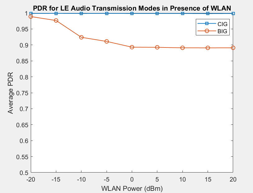
PDR of BIG and CIG Transmission Modes in the Presence of WLAN
To simulate the impact of WLAN power on the PDR performance of BIG and CIG transmission modes, these configuration parameters were specified.
Common parameters for CIG and BIG:
ISO interval: 0.030 seconds
Number of subevents: 12
Burst number: 6
Sub interval: 0.001 seconds
Audio packet size: 20 bytes
Audio data rate: 64 Kbps
Bluetooth power: -20 dBm
CIG:
Flush timeout: 2
BIG:
Repetition count: 2
BIG offset: 0.006 seconds
BIS spacing: 0.012 seconds
WLAN:
WLAN operating frequency band: 2.4 GHz
WLAN channel number: 7
Packet size: 200 bytes
Data rate: 35000 Kbps
Apart from the preceding parameters, all other configuration parameters are set to default.
The WLAN network consists of an access point (AP) and a station (STA). To create and configure the AP and STA, use the wlanNode (WLAN Toolbox) and wlanDeviceConfig (WLAN Toolbox) objects of WLAN® Toolbox. The WLAN power of both the AP and STA varies from -20 dBm to 20 dBm. The simulation runs with different seed values for CIG and BIG transmission modes. This plot shows how WLAN power impacts the network PDR in CIG and BIG transmission modes.

The PDR performance in CIG transmission mode is better than that in the BIG transmission mode because of the reliable transmission mechanism of CIS events and subevents. When you set the transmission mode to BIG, the PDR decreases with increase in WLAN power. When you set the transmission mode to CIG, the impact of WLAN power on the PDR is negligible.
Capture Bluetooth LE Packets to PCAP or PCAPNG file
To capture the packets at any Bluetooth nodes in a packet capture (PCAP) or packet capture next generation (PCAPNG) file, add the following code before you run the simulation. The packets are captured into individual PCAP/PCAPNG files for each of the Bluetooth LE node. The name of the PCAP file for a node is in the format: <NodeName_NodeID_yyyyMMdd_HHmmss>.<file_extension>. Node ID is a unique number generated internally for each node. Node ID is a read-only property for all the nodes. Use the blePCAPWriter object and specify the Bluetooth LE nodes to capture. Specify the file extension as "pcap" or "pcapng".
% clear packetCaptureObj; % Clear the packet capture handle if exists
% packetCaptureObj = blePCAPWriter(Node=nodes,FileExtension="pcap");
Visualize Captured IQ Samples
Capture the IQ samples by enabling the enableIQSampleCapture flag. To visualize the captured IQ samples, use the Signal Analyzer (Signal Processing Toolbox) app. For example, to visualize the IQ samples captured at the left sink node uncomment this code.
% if enableIQSampleCapture
%   leftSinkIQSamples = load(leftSink.Name+"_IQSamples"+".mat");
%   signalAnalyzer(leftSinkIQSamples.Waveform);
% end
Additionally, you can use this example to perform these tasks.
Add Custom Channel Classification for Bluetooth LE Nodes
Add Multiple Piconets and WLAN BSS to the Audio Network
For more information about how to simulate the preceding tasks, see the Simulate Noncollaborative Coexistence of WLAN, Bluetooth LE, and Bluetooth BR/EDR Networks example.
References
Bluetooth Technology Website. “Bluetooth Technology Website | The Official Website of Bluetooth Technology.” Accessed November 04, 2025. https://www.bluetooth.com/
Bluetooth Special Interest Group (SIG). "Bluetooth Core Specification". Version 6.1. https://www.bluetooth.com/
Local Functions
Custom Path Loss Model
Create a custom path loss model function by using the bluetoothPathLoss function and attach it to the wireless network simulator.
function rxData = updatePathLoss(rxInfo,txData,pathlossCfg)
    % Apply pathloss and update output signal
    rxData = txData;
    % Calculate distance between transmitter and receiver in meters
    distance = norm(rxData.TransmitterPosition - rxInfo.Position);
    pathloss = bluetoothPathLoss(distance,pathlossCfg);
    rxData.Power = rxData.Power - pathloss; % In dBm
    scale = 10.^(-pathloss/20);
    [numSamples, ~] = size(rxData.Data);
    rxData.Data(1:numSamples,:) = rxData.Data(1:numSamples,:)*scale;
end
See Also
Functions
Objects
wirelessNetworkSimulator(Wireless Network Toolbox) |bluetoothLENode|bluetoothLECISConfig