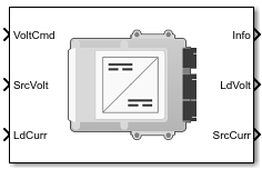
Bidirectional DC-DC
DC-to-DC converter that supports bidirectional boost and buck
Libraries:
Powertrain Blockset /
Energy Storage and Auxiliary Drive /
DC-DC
Description
The Bidirectional DC-DC block implements a DC-to-DC converter that supports bidirectional boost and buck (lower) operation. Unless the DC-to-DC conversion limits the power, the output voltage tracks the voltage command. You can specify electrical losses or measured efficiency.
Depending on your battery system configuration, the voltage might not be at a potential that is required by electrical system components such has inverters and motors. You can use the block to boost or buck the voltage. Connect the block to the battery and one of these blocks:
Mapped Motor
IM Controller
Interior PM Controller
Surface Mount PM Controller
To calculate the electrical loss during the DC-to-DC conversion, use Parameterize losses by.
| Parameter Option | Description |
|---|---|
|
|
Electrical loss calculated using a constant value for conversion efficiency. |
|
| Electrical loss calculated as a function of load current and voltage. DC-to-DC converter data sheets typically provide loss data in this format. When you use this option, provide data for all the operating quadrants in which the simulation will run. If you provide partial data, the block assumes the same loss pattern for other quadrants. The block does not extrapolate loss that is outside the range voltage and current that you provide. The block allows you to account for fixed losses that are still present for zero voltage or current. If you have Model-Based Calibration Toolbox™, click Calibrate Maps to virtually calibrate the 2-D lookup table using measured data. |
|
|
Electrical loss calculated using conversion efficiency that is a function of load current and voltage. When you use this option, provide data for all the operating quadrants in which the simulation will run. If you provide partial data, the block assumes the same efficiency pattern for other quadrants. The block:
|
Note
The block does not support inversion. The polarity of the input voltage matches the polarity of the output voltage.
Theory
The Bidirectional DC-DC block uses the commanded voltage and the actual voltage to determine whether to boost or buck (lower) the voltage. You can specify a time constant for the voltage response.
| If | Then |
|---|---|
| Voltcmd > SrcVolt | Boost |
| Voltcmd < SrcVolt | Buck |
The Bidirectional DC-DC block uses a time constant-based regulator to provide a fixed output voltage that is independent of load current. Using the output voltage and current, the block determines the losses of the DC-to-DC conversion. The block uses the conversion losses to calculate the input current. The block accounts for:
Bidirectional current flow
Source to load — Battery discharge
Load to source — Battery charge
Rated power limits
The block provides voltage control that is power limited based on these equations. The voltage is fixed. The block does not implement a voltage drop because the load current approximates DC-to-DC conversion with a bandwidth that is greater than the load current draw.
|
DC-to-DC converter load voltage | |
|
Power loss for single efficiency source to load | |
|
Power loss for single efficiency load to source | |
|
Power loss for tabulated efficiency | |
|
Source current draw from DC-to-DC converter | |
|
Source power from DC-to-DC converter |
Virtual Calibration
If you have Model-Based Calibration Toolbox, click Calibrate Maps to virtually calibrate the lookup table using measured data. The dialog box steps through these tasks.
Task | Description |
|---|---|
Import data | Import this loss data from a file. For example, open
Required data:
Collect data at steady-state operating conditions. To filter or edit the data, select Edit in Application. The Model-Based Calibration Toolbox Data Editor opens. |
Generate response models | The Model-Based Calibration Toolbox uses test plans to fit data to Gaussian process models (GPMs). To assess or adjust the response model fit, select Edit in Application. The Model-Based Calibration Toolbox Model Browser opens. For more information, see Model Assessment (Model-Based Calibration Toolbox). |
Generate calibration | Model-Based Calibration Toolbox calibrates the response models and generates calibrated table. To assess or adjust the calibration, select Edit in Application. The Model-Based Calibration Toolbox CAGE Browser opens. For more information, see Calibration Lookup Tables (Model-Based Calibration Toolbox). |
Update block parameters | Update these block lookup table and breakpoint parameters with the calibration.
|
Power Accounting
For the power accounting, the block implements these equations.
| Bus Signal | Description | Variable | Equations | ||
|---|---|---|---|---|---|
|
|
| Source power to DC-to-DC converter | Psrc | |
PwrBusLd | Load power from DC-to-DC converter | Pbus | |||
|
| PwrLoss | Converter power loss | Ploss | ||
|
| Not used | ||||
The equations use these variables.
| VoltCmd | DC-to-DC converter commanded output voltage |
| SrcVolt | Source input voltage to DC-to-DC converter |
| LdAmp | Load current of DC-to-DC converter |
| LdVolt | Load voltage of DC-to-DC converter |
| SrcAmp | Source current draw from DC-to-DC converter |
| τ | Conversion time constant |
| Vinit | Initial load voltage of the DC-to-DC converter |
| Plimit | Output power limit for DC-to-DC converter |
| Eff | Input to output efficiency |
| SrcPwr | Source power to DC-to-DC converter |
| LdPwr | Load power from DC-to-DC converter |
| PwrLoss | Power loss |
| LdVoltCmd | Commanded load voltage of DC-to-DC converter before application of time constant |
Examples

Build Full Electric Vehicle Model
Build a vehicle with a motor-generator, battery, direct-drive transmission, and powertrain control algorithms using the electric vehicle (EV) reference application.
Ports
Inputs
Output
Parameters
Extended Capabilities
Version History
Introduced in R2017b