주요 콘텐츠

Blade Element Theory

R2026b

Compute aerodynamic forces and moments using blade element theory

Since R2026b

Libraries:
Aerospace Blockset / Rotor Systems / Rotor Aerodynamics

Description

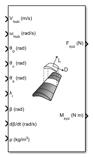
The Blade Element Theory block computes aerodynamic forces and moments generated by a rotating rotor using blade element theory. The block divides each rotor blade into spanwise elements, computes local aerodynamic forces using airfoil characteristics and flow conditions, and integrates these forces along the blade span and across all blades to obtain net hub forces and moments. The block expects the input velocities and provides the output forces and moments in the hub reference frame, which is a z-upward coordinate frame.

The block supports rigid blades with flap and optional lag motion, nonuniform and dynamic inflow distributions, and optional outputs of distributed aerodynamic loads. The Blade Element Theory block can be easily integrated with Dynamic Inflow (3-State) and Dynamic Inflow (Finite-State), and with the Rigid Blade (Flap and Lag) block for comprehensive rotorcraft modeling, including preliminary design analysis, performance evaluation, and stability analysis.

Limitations

The block does not support simulation in Accelerator mode, Rapid Accelerator mode, or code generation.

Ports

Input

expand all

Hub translational velocity, specified in the hub reference frame. If velocities are available in another reference frame, the required coordinate transformations to hub frame must be performed externally. The unit of this input depends on the Units parameter.

Data Types: double

Angular velocity of the rotor hub, in the hub reference frame.

Data Types: double

Collective blade pitch angle, specified as a scalar in radians.

Data Types: double

Lateral cyclic pitch angle, specified as a scalar in radians.

Data Types: double

Longitudinal cyclic pitch angle, specified as a scalar in radians.

Data Types: double

Nondimensional induced velocity component normal to the rotor disk.

  • Scalar specifies uniform inflow across the rotor disk.

  • Vector (1‑by‑Nri) specifies radially varying, axisymmetric inflow.

  • Matrix (Nb‑by‑Nri) specifies radially and azimuthally (blade‑resolved) varying inflow.

Here Nb is the number of blades and Nri is the number of radial locations at which inflow is available.

Data Types: double

Flap angles for each blade, specified in radians. These values are typically obtained from the Rigid Blade (Flap and Lag) block.

Flap rates for each blade, specified in rad/s. These values are typically obtained from the Rigid Blade (Flap and Lag) block.

Lag angles for each blade, specified in rad.

Dependencies

This port is enabled only when Include blade lag angle and rates is selected.

Data Types: double

Lag rates for each blade, specified in rad/s.

Dependencies

This port is enabled only when Include blade lag angle and rates is selected.

Data Types: double

Air density, specified as a positive scalar in specified units.

Tips

When used with the Dynamic Inflow (Finite-State) or Dynamic Inflow (3-State) blocks, ensure consistency of density values across blocks.

Data Types: double

Rotor speed, specified as a scalar in rad/s in body frame.

Dependencies

This port is enabled only when Rotor rotational speed source is set to Port.

Data Types: double

Output

expand all

Total force in the x‑y‑z direction, returned as a three‑element vector. It represents the sum of forces from all blades and segments, expressed in the hub reference frame. Units depend on the Units parameter.

Note

The Blade Element Theory block outputs hub forces and moments in the Z-upward hub reference frame with X-axis pointing towards the rear of the vehicle. To integrate with 6DOF (Euler Angles) blocks (which use NED frame with Z-downward), apply the required transformation. This differs from the Rotor and Multirotor blocks, which output forces directly in the Z-downward frame and do not require transformation for 6-DOF integration.

Data Types: double

Total moment in the x‑y‑z direction, returned as a three‑element vector and expressed in the hub reference frame. Units depend on the Units parameter. Similar to hub forces, to use with 6-DOF blocks, ensure the required transformation to NED frame is done.

Data Types: double

Spanwise distribution of normal force per unit length for each blade, returned as an array of size Nb-by-Nr, where Nb is the number of blades and Nr is the number of radial locations along the blade span where the force has been computed. The force values provided as output corresponds to mid points of the radial segments used in the computation.

The unit is either N/m or lbf/ft.

Dependencies

  • The unit of fz depends on the value of the Units parameter.

  • This port is enabled only when Output force distribution is selected.

Data Types: double

Spanwise distribution of tangential force per unit length for each blade, returned as an array of size Nb-by-Nr, where Nb is the number of blades and Nr is the number of radial locations along the blade span where the force has been computed. The force values provided as output corresponds to mid points of the radial segments used in the computation.

The unit is either N/m or lbf/ft.

Dependencies

  • The unit of fx depends on the value of the Units parameter.

  • This port is enabled only when Output force distribution is selected.

Data Types: double

Spanwise distribution of radial force per unit length for each blade, returned as an array of size Nb-by-Nr, where Nb is the number of blades and Nr is the number of radial locations along the blade span where the force has been computed. The force values provided as output corresponds to mid points of the radial segments used in the computation.

The unit is either N/m or lbf/ft.

Dependencies

  • The unit of fr depends on the value of the Units parameter.

  • This port is enabled only when Output force distribution is selected.

Data Types: double

Rotor advance ratio, returned as a real scalar, representing the ratio of the total horizontal hub velocity to the tip speed. Calculated as μ = √(uh² + vh²) / (ΩR), where uh and vh are the horizontal components of hub translational velocity, Ω is the angular velocity of the rotor in radians per second, and R is the rotor radius.

The computed value depends on the input hub translational velocity (Vhub) and is unconstrained. However, if used as input to the Inflow block, consider its input limits of [‑1, 4].

Dependencies

This port is enabled only when Output velocity ratios is selected.

Data Types: double

Normal velocity ratio, returned as a real scalar, representing the ratio of the vertical hub velocity to the tip speed. Calculated as μz = w / (ΩR), where w is the vertical component of hub translational velocity, Ω is the angular velocity of the rotor in radians per second, and R is the rotor radius.

The computed value depends on the input hub translational velocity (Vhub) and is unconstrained. However, if used as input to the Inflow block, consider its input limits of [‑1, 4].

Dependencies

This port is enabled only when Output velocity ratios is selected.

Data Types: double

Parameters

expand all

To edit block parameters interactively, use the Property Inspector. From the Simulink® Toolstrip, on the Simulation tab, in the Prepare gallery, select Property Inspector.

Main

Input and output ports and parameter units, specified as Metric (MKS), English (Velocity in ft/s), or English (Velocity in kts).

UnitsVhubRadiusFhubMhubElemental Force DistributionDensity
Metric (MKS)

m/s

Meters

N

N·m

N/m

kg/m3

English (Velocity in ft/s)

ft/s

Feet

lbf

lbf·ft

lbf/ft

slug/ft3

English (Velocity in kts)

kts

Feet

lbf

lbf·ft

lbf/ft

slug/ft3

Programmatic Use

Block Parameter: units
Type: character vector
Values: Metric (MKS) | English (Velocity in ft/s) | English (Velocity in kts)
Default: Metric (MKS)

Source of the angular velocity of the rotor, specified as one of Dialog or Port.

Programmatic Use

Block Parameter: omegaSrc
Type: character vector
Values: Dialog | Port
Default: Dialog

Rotational speed of rotor, specified as a real scalar in radians per second.

Dependencies

This parameter is visible when the Rotational Speed Source parameter is set to Dialog.

Programmatic Use

Block Parameter: omega
Type: double
Values: 41.2596 | real scalar
Default: 41.2596

Number of blades in the rotor, specified as a positive integer scalar. This value determines the required dimensions of blade‑resolved inputs and outputs.

Programmatic Use

Block Parameter: Nb
Type: double
Values: positive integer scalar
Default: 4

Rotor radius, specified as a nonzero scalar in m or ft. This is the distance from the center of the rotor hub to the tip of the rotor blades, specified by R in the equations for μ and μz.

Dependencies

The unit of Rotor radius depends on the value of the Units parameter.

Programmatic Use

Block Parameter: radius
Type: double
Values: 5.08 | real positive scalar
Default: 5.08

Non‑dimensional radial locations defining blade element boundaries, specified as a 1-by-(Nr+1) vector with strictly increasing values in the range [0,1], where Nr is the number of blade elements.

Programmatic Use

Block Parameter: bladeElements
Type: real vector
Values: [0.1 0.2 0.3 0.4 0.5 0.6 0.7 0.8 0.9] | 1-by-(Nr+1) vector in the range [0,1]
Default: [0.1 0.2 0.3 0.4 0.5 0.6 0.7 0.8 0.9]

Select this option to return spanwise normal fz, tangential fx, and radial fr force distributions.

Dependencies

When selected, this option enables the fz, fx, and fr output ports.

Programmatic Use

Block Parameter: outLoadDistribution
Type: character vector
Values: 'on' | 'off'
Default: 'off'

Select this option to return rotor advance ratio μ and normal velocity ratio μz.

Dependencies

When selected, this option enables the μ and μz output ports.

Programmatic Use

Block Parameter: outVelocityRatio
Type: character vector
Values: 'on' | 'off'
Default: 'off'

Blade

Flap hinge offset, specified as a real scalar in the range 0 to 1. This represents the distance from the hub center to the physical or effective flap hinge, expressed as a fraction of blade radius. This offset affects the centrifugal stiffening and flapping dynamics of the blade.

Programmatic Use

Block Parameter: flapHingeOffset
Type: double
Values: real scalar
Default: 0.06

Data Types: double

Chord distribution, specified as a real positive scalar or real 2‑D matrix. This parameter defines the nondimensional chord distribution along the blade span, expressed as a fraction of blade radius.

  • Scalar — Specifies a constant chord along the entire blade span.

  • Matrix — Specifies a spanwise‑varying chord distribution using a 2‑by‑N matrix. The first row contains non‑dimensional radial positions, strictly increasing in [0, 1]. The second row contains the corresponding positive chord values. For example: [r1​ r2​ …rN​; c1​ c2​ …cN​]

The chord value at any required spanwise location is determined using linear interpolation within the specified range. For locations outside the provided range, the chord value is held constant at the nearest boundary value.

Programmatic Use

Block Parameter: chordDistribution
Type: double
Values: 0.0628 | real positive scalar | real 2‑D matrix
Default: 0.0628

Data Types: double

Blade twist model, specified as one of Linear, Ideal or Custom.

Programmatic Use

Block Parameter: twistType
Type: character vector
Values: Linear | Ideal | Custom
Default: Linear

Blade root pitch angle, specified as a scalar in radians.

Dependencies

This parameter is visible when Blade twist is set to Linear.

Programmatic Use

Block Parameter: thetaRoot
Type: double
Values: real scalar
Default: 0.15

Blade twist angle, specified as a scalar in radians.

Dependencies

This parameter is visible when Blade twist is set to Linear.

Programmatic Use

Block Parameter: thetaTwist
Type: double
Values: real scalar
Default: -0.15

Blade tip pitch angle, specified as a scalar in radians.

Dependencies

This parameter is visible when Blade twist is set to Ideal.

Programmatic Use

Block Parameter: thetaTip
Type: double
Values: real scalar
Default: -0.17

Geometric twist distribution, specified as a real 2‑D matrix. Enter a 2‑row matrix where the first row contains non‑dimensional radial positions, strictly increasing in [0, 1], and the second row contains corresponding twist values in degrees. For example: [r1​ r2​ r3​; t1​ t2​ t3​]

The twist at any desired spanwise location is determined by linear interpolation within the provided range. For locations outside the specified range, the twist value is held constant at the nearest boundary value (flattened).

Dependencies

This parameter is visible when Blade twist is set to Custom.

Programmatic Use

Block Parameter: twistDistribution
Type: double
Values:[0 0.25 0.5 0.75 1; 0 -3 -6 -9 -12] | real 2‑D matrix
Default: [0 0.25 0.5 0.75 1; 0 -3 -6 -9 -12]

Data Types: double

Select this option to include blade lag degrees of freedom.

Dependencies

When selected, this option exposes the ζ and dζ/dt input ports. When enabled, ζ and dζ/dt are incorporated into the transformation of hub velocities to local blade velocities, allowing for more accurate modeling of blade dynamics.

Programmatic Use

Block Parameter: includeBladeLag
Type: character vector
Values: 'on' | 'off'
Default: 'off'

Lag hinge offset, specified as a real scalar in the range 0 to 1. This represents the distance from the hub center to the physical or effective lag hinge, expressed as a fraction of blade radius. This offset affects the centrifugal stiffening and lag dynamics of the blade.

Dependencies

This parameter is visible when the Include blade lag angle and rates is selected.

Programmatic Use

Block Parameter: lagHingeOffset
Type: double
Values: real scalar
Default: 0.06

Data Types: double

Airfoil

Method for specifying lift coefficient data, specified as one of:

  • Lift curve slope (per rad) — Uses a constant lift-curve slope, assuming a linear relationship between lift coefficient and angle of attack.

  • Lift coefficient matrix [alpha(deg); cl(non-dimensional)] — Uses a lookup table of lift coefficient as a function of angle of attack.

Programmatic Use

Block Parameter: liftCoeffSpec
Type: character vector
Values: 'Lift curve slope (per rad)' | 'Lift coefficient matrix [alpha(deg); cl(non-dimensional)]'
Default: 'Lift curve slope (per rad)'

Lift coefficient, specified as a nonzero positive scalar or 2‑D matrix. This parameter defines the lift characteristics of the blade airfoil section and is used to compute aerodynamic lift at each blade element.

When Lift coefficient specification is set to Lift curve slope (per rad):

  • Specify a nonzero positive scalar representing the lift-curve slope clα in units of per radian.

  • The default value 5.73 corresponds to the lift-curve slope for a NACA 0012 airfoil.

When Lift coefficient specification is set to Lift coefficient matrix [alpha(deg); cl(non-dimensional)]:

  • Specify a 2‑by‑N matrix of the form [α1 α2 …αN; cl,1 cl,2 …cl,N], where the first row contains angle of attack values α in degrees in strictly increasing order, and the second row contains corresponding non‑dimensional lift coefficient values. Lift coefficient values can be negative, zero, or positive.

  • The block uses linear interpolation to evaluate lift coefficient at the local angle of attack. For α values outside the specified range, cl is held constant at the nearest boundary value (clamped).

Programmatic Use

Block Parameter: liftData
Type: double
Values: 5.73 | nonzero positive scalar | 2‑D matrix
Default: 5.73

Method for specifying drag coefficient data, specified as one of:

  • Mean drag coefficient (non-dimensional) — Uses a constant mean drag coefficient, independent of angle of attack.

  • Drag coefficient matrix [alpha(deg); cd(non-dimensional)] — Uses a lookup table of drag coefficient as a function of angle of attack.

Programmatic Use

Block Parameter: dragCoeffSpec
Type: character vector
Values: 'Mean drag coefficient (non-dimensional)' | 'Drag coefficient matrix [alpha(deg); cd(non-dimensional)]'
Default: 'Mean drag coefficient (non-dimensional)'

Drag coefficient, specified as a non‑negative scalar or 2‑D matrix. This parameter defines the drag characteristics of the blade airfoil section and is used to compute aerodynamic drag at each blade element.

When Drag coefficient specification is set to Mean drag coefficient (non-dimensional):

  • Specify a non‑negative scalar representing the mean drag coefficient cd0 (non‑dimensional).

  • The default value 0.008 is a typical mean drag coefficient for a NACA 0012 airfoil.

When Drag coefficient specification is set to Drag coefficient matrix [alpha(deg); cd(non-dimensional)]:

  • Specify a 2‑by‑N matrix of the form [α1 α2 …αN; cd,1 cd,2 …cd,N], where the first row contains angle of attack values α in degrees in strictly increasing order, and the second row contains corresponding non‑dimensional drag coefficient values. Drag coefficient values must be non‑negative.

  • The block uses linear interpolation to evaluate drag coefficient at the local angle of attack. For α values outside the specified range, cd is held constant at the nearest boundary value (clamped).

Programmatic Use

Block Parameter: dragData
Type: double
Values: 0.008 | non‑negative scalar | 2‑D matrix
Default: 0.008

Inflow

Select this option to specify radial locations corresponding to inflow input values.

Note

When this option is not selected, Nri = 1 or Nr (where Nri is the number of columns in the inflow input and Nr is the number of blade segments). The inflow input is expected to be either a scalar for uniform inflow, or a vector/matrix with values corresponding to the mid-points of the blade segments as specified through the Non-dimensional blade element edges parameter. When selected, Nri equals the length of the Radial distribution for inflow input parameter, and need not be equal to Nr.

Dependencies

When selected, this option exposes the Radial distribution for inflow input parameter.

Programmatic Use

Block Parameter: customInflow
Type: character vector
Values: 'on' | 'off'
Default: 'off'

Radial distribution for inflow input, specified as a real scalar or real vector. This parameter defines the non‑dimensional radial locations at which the induced inflow input is specified, expressed as a fraction of the rotor radius.

The values must be strictly increasing and lie within the closed interval 0≤r/R≤1.

The number of elements must match the number of columns in the inflow input signal when the inflow input is provided as a vector or matrix.

Outside the specified range, inflow values are flattened.

Dependencies

This parameter is enabled only when the Custom inflow distribution parameter is selected.

When enabled, the block uses linear interpolation to evaluate the induced inflow at the required blade element locations based on the specified radial distribution.

Programmatic Use

Block Parameter: inflowRadialDistribution
Type: double
Values: [0.15 0.25 0.35 0.45 0.55 0.65 0.75 0.85] | real scalar | real vector
Default: [0.15 0.25 0.35 0.45 0.55 0.65 0.75 0.85]

Algorithms

Use the Blade Element Theory block to compute the aerodynamic forces and moments generated by a rotating rotor using blade element theory. The block evaluates aerodynamic loads at discrete blade elements and integrates these loads along the blade span and across all blades.

The Blade Element Theory block computes aerodynamic forces only. Blade flap and optional lag motion are provided as inputs and are not solved internally.

Blade Element Discretization

The block divides each rotor blade into spanwise blade elements using the non‑dimensional radial locations specified by the Blade element edges parameter. These locations define the extremities of each blade element.

From these radial locations, the block computes the spanwise length and midpoint of each blade element. All aerodynamic quantities are evaluated at the blade element midpoints.

Note

The Blade Element Theory block does not separately include root cutout or tip loss factor. It is expected that the limits mentioned exclude the aerodynamically inefficient portion of the blade.

Per‑Blade and Per‑Element

For each simulation step, the block loops over:

  • Each blade

  • Each blade element along the span

At each blade element, the block evaluates local flow conditions, aerodynamic coefficients, and elemental forces.

Inflow and Local Geometry Evaluation

The block evaluates the induced inflow at each blade element using the inflow input. The inflow can be specified as:

  • A scalar uniform inflow

  • A radially varying, axisymmetric inflow

  • Spanwise and azimuthally varying inflow

When the Custom inflow distribution option is enabled, the block interpolates the inflow input defined at the specified radial locations through the Inflow radial distribution parameter to obtain the inflow at each blade element midpoint.

The Blade Element Theory block also evaluates the local chord and geometric twist at each blade element. When these quantities are provided as distributions, the block uses linear interpolation. For locations outside the specified range, values are held constant at the nearest boundary.

Local Geometry and Pitch

At each blade element:

  • Evaluate the local chord:

    • Use a constant value if specified as a scalar.

    • Use linear interpolation if specified as a matrix.

  • Evaluate the local geometric twist:

    • Linear

    • Ideal

    • Custom, using linear interpolation within the provided range and clamping outside the range.

  • Combine collective, cyclic, and geometric contributions to compute the local pitch angle.

Local Velocities and Aerodynamic Angles

Using hub velocities, rotor speed, induced inflow, and blade flap and lag inputs, the block computes the local relative flow velocity at each blade element. From this relative velocity and local blade pitch, the block computes the local angle of attack. Blade flap and lag inputs influence the local velocity calculation but are not solved within the block. Compute flap and lag motion by solving the rigid blade flap-lag equations, such as implemented in the Rigid Blade (Flap and Lag) block.

Compute the relative flow magnitude:

U=Up2+Ut2

Compute the local inflow angle ϕ and angle of attack α:

α=θ−ϕ=θ−tan−1(UpUt)

Aerodynamic Forces

At each blade element, the block computes elemental lift and drag using the specified airfoil model. Lift and drag coefficients can be provided as constants or as tabulated data.

These elemental force components are computed in the blade reference frame.

  • If provided as constants:

    cl=clα(θ−ϕ)cd=cd0

  • If provided as matrices:

    cl=f(α)cd=f(α)

The block resolves elemental lift and drag into:

  • Normal force

  • Tangential force

  • Radial force

Use interpolation to evaluate coefficients at the current operating point.

Force and Moment Integration

The Blade Element Theory block integrates elemental forces along the blade span and sums contributions from all blades to compute net forces and moments at the rotor hub.

When enabled, the block also outputs the spanwise distributions of normal, tangential, and radial forces, which can be used as inputs to Dynamic Inflow (Finite-State),Dynamic Inflow (3-State) or Rigid Blade (Flap and Lag) blocks.

Note

All physical quantities in these equations are dimensional (for example, chord c, relative velocity Urel, and air density ρ).

Compute elemental lift and drag as:

L=12ρUrel2ccldrD=12ρUrel2ccddr

Resolve elemental forces into:

fz=(Lcosϕ−Dsinϕ)cosβfx=Lsinϕ+Dcosϕfr=−(Lcosϕ−Dsinϕ)sinβ

The block sums elemental forces across all blade elements and blades to compute the net hub forces and moments.

Note

The Blade Element Theory block accepts input velocities and outputs forces and moments in the hub reference frame, with the Z-axis pointing upward and the X-axis pointing towards the rear of the vehicle.

  • For forward flight at speed V, the hub velocity input is Vhub = [-V; 0; 0].

  • Hub forces (Fhub = [H; Y; T]):

    • H — Drag force in the disk plane, positive rearward (opposing forward velocity)

    • Y — Side force in the disk plane, positive towards the advancing side

    • T — Thrust normal to the disk plane, positive upward

  • Hub moments (Mhub = [Mx; My; Q]):

    • Mx — Rolling moment, positive toward the retreating side

    • My — Pitching moment, positive rearward

    • Q — Rotor shaft torque about the shaft axis, positive when external torque is required to turn the rotor

References

[1] Leishman, Gordon J. Principles of Helicopter Aerodynamics with CD Extra. Cambridge University Press, 2006.

[2] Johnson, Wayne. Rotorcraft Aeromechanics. Vol. 36. Cambridge University Press, 2013.

Version History

Introduced in R2026b