Rigid Blade (Flap and Lag)
R2026bRigid Blade (Flap and Lag) block
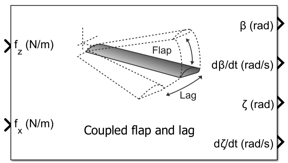
To add a block to a model, double-click the canvas and start typing the block name. Then, select the block from the list.
Libraries:
Aerospace Blockset /
Rotor Systems /
Blade Components
Description
The Rigid Blade (Flap and Lag) block models coupled flap and lag dynamics or isolated flap and lag dynamics of rigid rotor blades in response to distributed aerodynamic forces. The outputs of this block can feed Blade Element Theory and other aerodynamic blocks for rotorcraft analysis.
Limitations
The block does not support simulation in Accelerator mode, Rapid Accelerator mode, or code generation.
Ports
Input
Output
Parameters
To edit block parameters interactively, use the Property Inspector. From the Simulink® Toolstrip, on the Simulation tab, in the Prepare gallery, select Property Inspector.
Main
Input and output ports and parameter units, specified as Metric
(MKS) or English.
| Units | Radius | Elemental Force Distribution | Flap/Lag Inertia | Flap Spring Constant | Flap/Lag Damping |
|---|---|---|---|---|---|
Metric
              (MKS)
| Meters | N/m | kg·m2 | N·m/rad | N·m·s/rad |
English
| Feet | lbf/ft | slug·ft2 | lbf·ft/rad | lbf·ft·s/rad |
Programmatic Use
Block Parameter:
units |
| Type: character vector |
Values:
Metric (MKS) | English |
Default:
Metric (MKS) |
Blade dynamics model to simulate, specified as one of
Coupled flap and lag— Solves the fully coupled flap and lag dynamics and enables all input and output ports.Isolated flap— Solves only the out‑of‑plane flap dynamics. Enables thefzinput and theβanddβ/dtoutputs.Isolated lag— Solves only the in‑plane lag dynamics. Enables thefxinput and theζanddζ/dtoutputs.
Programmatic Use
Block Parameter:
model |
| Type: character vector |
Values:
Coupled flap and lag | Isolated flap |
Isolated lag |
Default:
Coupled flap and lag |
Source of the angular velocity of the rotor, specified as one of
Dialog or Port.
Programmatic Use
Block Parameter:
omegaSrc |
| Type: character vector |
Values:
Dialog | Port |
Default:
Dialog |
Rotational speed of rotor, specified as a real scalar in radians per second.
Dependencies
This parameter is visible when the Rotational Speed Source parameter is set to
Dialog.
Programmatic Use
Block Parameter:
omega |
| Type: double |
Values:
41.2596 | real scalar |
Default:
41.2596 |
Number of rotor blades, specified as a positive integer scalar. This parameter defines the blade count used to size the input force arrays and the output angle and rate vectors.
Programmatic Use
Block Parameter:
Nb |
| Type: double |
| Values: positive integer scalar |
Default:
4 |
Data Types: double
Rotor radius, specified as a nonzero scalar in m or ft. This is the distance from the center of the rotor hub to the tip of the rotor blades.
Dependencies
The unit of Blade radius depends on the value of the Units parameter.
Programmatic Use
Block Parameter:
radius |
| Type: double |
Values:
5.08 m | real positive scalar |
Default:
5.08 m |
Source of radial locations, specified as one of Uniform distribution based on force input or Custom distribution. This parameter determines how the radial positions along the rotor blade are specified for aerodynamic computations.
Uniform distribution based on force input- The entire length of the rotor blade is divided into equal segments based on the number of radial locations Nr specified in the force input. For example, if the number of columns in force input is 10, the blade span will be divided into 10 equal segments, as shown in the figure.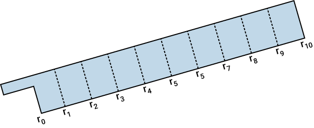
Custom distribution- You can specify non-uniform radial positions along the blade, using the parameter Non-dimensional radial element edges (default: -1 for uniform distribution).
Programmatic Use
Block Parameter:
radSrc |
| Type: char vector |
Values:
Uniform distribution based on force input |
Custom distribution |
Default:
Uniform distribution based on force input |
Custom radial segment limits (non-dimensional), specified as the sentinel value -1 (default) to use uniform distribution, or as a real nonnegative strictly increasing vector with values in [0 1] for custom distribution. The length of the vector should be one greater than Nr, the number of columns in the force input. It is expected that the input force values are computed or obtained at the mid-points of the radial segments specified through the parameter. For example, if the user inputs the parameter as, [r0 r1 r2 r3 r4 r5 r6 r7 r8 r9 r10], with r0>=0, and r10<=1, a sample blade segment distribution is as shown in the figure and Nr will be 10. It is expected that the range r0 to r10 is the aerodynamically effective region of the blade and the integration to compute force is done only in this region. The accuracy of the computed inflow distribution can be influenced by the radial discretization, including the number and spacing of blade elements, as well as the portion of the aerodynamically effective blade span represented by the specified radial segments.
Dependencies
This parameter is visible when Radial locations source
is set to Custom distribution.
Programmatic Use
Block Parameter:
radDistr |
| Type: double |
| Values: real scalar | real nonnegative strictly increasing vector with values in [0 1] |
Default:
-1 |
Blade
Flap hinge offset, specified as a real scalar in the range 0 to 1. This represents the distance from the hub center to the physical or effective flap hinge, expressed as a fraction of blade radius. This offset affects the centrifugal stiffening and flapping dynamics of the blade.
Dependencies
This parameter is visible when the Model parameter is set to Coupled flap and lag or Isolated flap.
Programmatic Use
Block Parameter:
flapHingeOffset
|
| Type: double |
| Values: real scalar |
Default:
0.06
|
Data Types: double
Flap hinge inertia, specified as a real positive scalar or vector of length Nb. This represents the mass moment of inertia of the blade about the flap hinge, and is its resistance to out‑of‑plane angular acceleration. The unit of this parameter depends on the Units parameter.
Dependencies
This parameter is visible when the Model parameter is set to
Coupled flap and lag or Isolated flap.
Programmatic Use
Block Parameter:
flapInertia |
| Type: double |
| Values: real positive scalar or vector of length Nb |
Default:
1084.7 |
Data Types: double
Nondimensional flap natural frequency of out‑of‑plane (flapping) motion, in per rev, specified as a real positive scalar or vector of length Nb. This value is based on structural properties and excludes aerodynamic excitation.
Dependencies
This parameter is visible when the Model parameter is set to
Coupled flap and lag or Isolated flap.
Programmatic Use
Block Parameter:
flapFrequency |
| Type: double |
| Values: real positive scalar or vector of length Nb |
Default:
1.04 |
Flap spring constant, specified as a real nonnegative scalar or vector of length Nb. This represents the restoring torque per unit flap angle at the flap hinge. The unit of this parameter depends on the Units parameter.
Dependencies
This parameter is visible when the Model parameter is set to
Coupled flap and lag or Isolated flap.
Programmatic Use
Block Parameter:
flapStiffness |
| Type: double |
| Values: real nonnegative scalar or vector of length Nb |
Default:
0 |
Flap damping coefficient, specified as a real nonnegative scalar or vector of length Nb. This represents the viscous damping coefficient at the flap hinge, producing a retarding torque proportional to flap angular velocity. Aerodynamic damping is not included. The unit of this parameter depends on the Units parameter.
Dependencies
This parameter is visible when the Model parameter is set to
Coupled flap and lag or Isolated flap.
Programmatic Use
Block Parameter:
flapDamping |
| Type: double |
| Values: real nonnegative scalar or vector of length Nb |
Default:
0 |
Precone angle, specified as a real nonnegative scalar in degrees. This represents the fixed upward angle of the blade relative to the hub plane. This parameter is effective only when the flap spring constant is nonzero.
Dependencies
This parameter is visible when the Model parameter is set to
Coupled flap and lag or Isolated flap.
Programmatic Use
Block Parameter:
precone |
| Type: double |
| Values: real nonnegative scalar |
Default:
2.5 |
Lag hinge offset, specified as a real scalar in the range 0 to 1. This represents the offset from hub center to the physical or effective lag hinge, expressed as a fraction of blade radius. This offset affects the centrifugal stiffening and lag dynamics of the blade.
Dependencies
This parameter is visible when the Model parameter is set to
Coupled flap and lag or Isolated lag.
Programmatic Use
Block Parameter:
lagHingeOffset |
| Type: double |
| Values: real scalar |
Default:
0.06 |
Lag hinge inertia, specified as a real positive scalar or vector of length Nb. This represents the mass moment of inertia about the lag hinge, and is its resistance to angular acceleration in the in‑plane (lead‑lag) direction. The unit of this parameter depends on the Units parameter.
Dependencies
This parameter is visible when the Model parameter is set to
Coupled flap and lag or Isolated lag.
Programmatic Use
Block Parameter:
lagInertia |
| Type: double |
| Values: real positive scalar or vector of length Nb |
Default:
1084.7 |
Data Types: double
Nondimensional lag natural frequency of in‑plane (lead–lag) motion, in per rev, specified as a real positive scalar or vector of length Nb. This value is based on structural properties and excludes aerodynamic excitation.
Dependencies
This parameter is visible when the Model parameter is set to
Coupled flap and lag or Isolated lag.
Programmatic Use
Block Parameter:
lagFrequency |
| Type: double |
| Values: real positive scalar or vector of length Nb |
Default:
0.29 |
Damping coefficient at the lag hinge, specified as a real nonnegative scalar or vector of length Nb, providing mechanical damping torque proportional to lag angular velocity. Aerodynamic damping is not included. The unit of this parameter depends on the Units parameter.
Dependencies
This parameter is visible when the Model parameter is set to
Coupled flap and lag or Isolated lag.
Programmatic Use
Block Parameter:
lagDamping |
| Type: double |
| Values: real nonnegative scalar or vector of length Nb |
Default:
4067.5 |
Algorithms
This block computes rigid‑blade flap and lag dynamics using a small‑angle formulation. The block operates on distributed aerodynamic force inputs to compute flap and lag moments and integrates the corresponding equations of motion.
Rotor speed, Ω, is obtained either as a block parameter (when Rotor Rotational
Speed Source is set to Dialog) or as an input signal
(when set to Port).
Distributed force inputs are provided over the blade span as normal (fz) and in‑plane (fx) forces per unit span. The inputs are sized Nb-by-Nr, where Nb is the number of blades and Nr is the number of radial segments.
The blade span is discretized based on the Radial locations source
parameter.
For a uniform distribution, the span is divided into Nr equal segments. For custom distribution, the input to the parameter ‘Non dimensional radial element edges’ is considered as the limits of the blade elements. For example, if the user specifies radial node locations {r0, r1,…,rNr}, the segment lengths will be computed as dri= ri+1 -ri.
It is assumed that the provided force values are at the mid points of these segments. The dimensional mid points of the segments will be yi = R(ri +dri/2)
For each blade b, flap and lag moments are computed by integrating contributions from all radial segments:
Note that only the force contributions from the portion of the blade beyond the flap hinge offset (eβ) is considered in computation of flap moment. Similarly, for lag moment computation, only the portion of the blade beyond the lag hinge offset (eζ) is considered. Also, in the block implementation, flap and lag moments are computed by summing the contributions from discrete blade segments rather than continuous integration.
The rigid‑blade equations of motion are second‑order ordinary differential equations defined per blade. For the Coupled Flap and Lag mode:
The state vector is defined as , with each component of size Nb×1. The total number of states is 4Nb for the coupled model and 2b for isolated flap or isolated lag models. The equations of motion are numerically integrated to obtain blade flap and/or lag angles and rates. Distributed force inputs are updated at each time step and used to recompute the corresponding moments.
For Isolated flap mode, only the first equation is solved, with the coupling term omitted. For Isolated lag mode, only the second equation is solved, with Coriolis terms omitted.N
References
[1] Leishman, Gordon J. Principles of Helicopter Aerodynamics with CD Extra. Cambridge University Press, 2006.
[2] Johnson, Wayne. Rotorcraft Aeromechanics. Vol. 36. Cambridge University Press, 2013.
Version History
Introduced in R2026b

