802.11be Packet Error Rate Simulation for Uplink Trigger-Based Format
This example shows how to measure the packet error rate of an IEEE® 802.11be™ (Wi-Fi 7) extremely high-throughput (EHT) uplink, trigger-based (TB) format.
Introduction
The 802.11be [1] EHT trigger-based (EHT TB) format allows for OFDMA or MU-MIMO transmission in the uplink. The AP controls the EHT TB transmission and provides the required parameters to all stations (STAs) participating in the transmission using a trigger frame. Each STA transmits an EHT TB packet simultaneously, when triggered by the AP as shown in the following diagram.
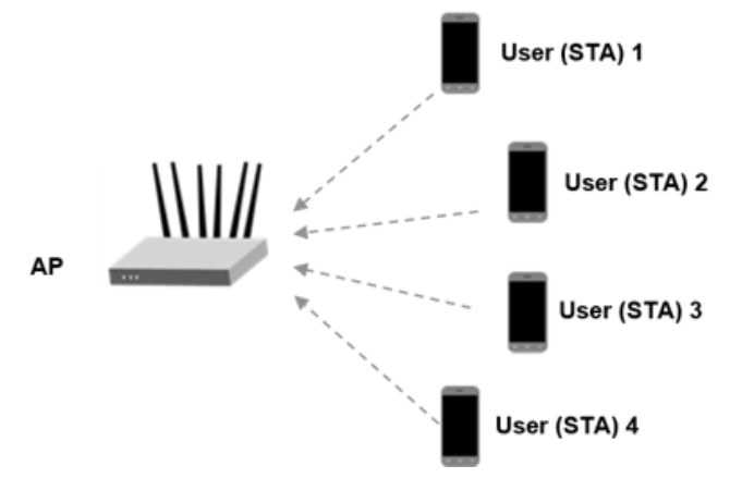
This example uses an end-to-end simulation to determine the packet error rate of an EHT TB link for four STAs in an MU-MIMO configuration. The transmitter sends multiple packets at each SNR point, with no impairments apart from channel and noise. The receiver demodulates the packets and recovers the PSDUs for each STA. The example compares the recovered PSDUs to the transmitted PSDUs to determine the number of packet errors, and hence, the packet error rate for all users. The receiver performs packet detection, timing synchronization, and symbol equalization. This example does not perform frequency offset correction. The EHT TB processing chain is shown in the following diagram.

The receiver performs a minimum-mean-square-error-based ordered successive interference cancellation (MMSE-SIC) process for data equalization [2]. To avoid error propagation in the cancellation stage, data streams for all STAs are sorted in descending order based on the channel state information and equalized sequentially. This diagram shows the MMSE-SIC equalization procedure.

Equalization Method
In this example, you can specify the equalization method as 'mmse' or 'mmse-sic'. The default equalizer is 'mmse-sic'.
equalizationMethod = 'mmse-sic';User Configuration
This example configures the allocation and transmit parameters for multiple uplink STAs using an ehtTBSystemConfig object.
cfgSys = ehtTBSystemConfig('CBW20','NumUsers',4);
In a trigger-based transmission some parameters are the same for all uplink users, while some can differ. The User property of cfgSys contains a cell array of user configurations. Each element of the cell array is an object which sets the parameters of an individual user. In this example, all users have the same transmission parameters.
% These parameters are the same for all users in the MU-MIMO system
cfgSys.EHTLTFType = 4;      % EHT-LTF compression mode
cfgSys.GuardInterval = 3.2; % Guard interval type
numRx = 8;                  % Number of receive(AP) antennas

% The individual parameters for each user are specified below
numUsers = numel(cfgSys.User); % Number of uplink users
for userIdx = 1:numUsers
    cfgSys.User{userIdx}.NumTransmitAntennas = 1;
    cfgSys.User{userIdx}.NumSpaceTimeStreams = 1;
    cfgSys.User{userIdx}.SpatialMapping = 'Direct';
    cfgSys.User{userIdx}.MCS = 7;
    cfgSys.User{userIdx}.APEPLength = 1e3;
    cfgSys.User{userIdx}.ChannelCoding = 'LDPC';
end
allocInfo = ruInfo(cfgSys);
Use a wlanEHTTBConfig object to configure a trigger-based transmission for a single user within the system. The method userConfig configures the transmission for all users. This example creates a cell array of four EHT TB objects which describes the transmission of four users.
cfgTB = userConfig(cfgSys);
Simulation Parameters
For each SNR point (dB) in the snr vector, the example generates a number of packets. These are passed through a channel and demodulated to determine the packet error rate.
snr = 20:2:24;

% The sample rate and field indices for the EHT TB packet are the same for
% all users. Use the trigger configuration of the first user to get the
% sample rate and field indices of the EHT TB PPDU.
fs = wlanSampleRate(cfgTB{1});    % Same for all users
ind = wlanFieldIndices(cfgTB{1}); % Same for all users
Channel Configuration
This example uses a TGax NLOS indoor channel model with delay profile Model-B. Model-B is in non-line of sight (NLOS) when the distance between the transmitter and receiver is greater than or equal to 5 meters. This is described further in wlanTGaxChannel. In this example all STAs are at the same distance from the AP.
tgaxBase = wlanTGaxChannel;
tgaxBase.SampleRate = fs;
tgaxBase.TransmissionDirection = 'Uplink';
tgaxBase.TransmitReceiveDistance = 10;
chanBW = cfgSys.ChannelBandwidth;
tgaxBase.ChannelBandwidth = chanBW;
tgaxBase.NumReceiveAntennas = numRx;
tgaxBase.NormalizeChannelOutputs = false;
The example creates individual channels for each of the four users. Each channel is a clone of tgaxBase, but with a different UserIndex property, and is stored in a cell array tgax. The UserIndex property of each individual channel is set to provide a unique channel for each user. This example uses a random channel realization for each packet by randomly varying the UserIndex property for each transmitted packet.
% A cell array stores the channel objects, one per user
tgax = cell(1,numUsers);
for userIdx = 1:numUsers
    tgax{userIdx} = clone(tgaxBase);
    tgax{userIdx}.NumTransmitAntennas = cfgSys.User{userIdx}.NumTransmitAntennas;
    tgax{userIdx}.UserIndex = userIdx;
end
Processing SNR Points
For each SNR point, the example tests a number of packets and calculates the packet error rate. The pre-EHT preamble of 802.11be is backwards compatible with 802.11ax™. Therefore, this example uses the timing synchronization components of an 802.11ax waveform to synchronize the EHT waveform at the receiver. For each user, the example follows these processing steps to create a waveform at the receiver containing all four users:
To create an EHT TB waveform, create and encode a PSDU for each user, based on predefined user parameters.
Pass the waveform for each user through an indoor TGax channel model. The randomly varying
UserIndexproperty of the channel creates different channel realizations for each user. This results in different spatial correlation properties for each user.Scale and combine the waveforms for all EHT TB users to ensure the same SNR for each user after the addition of noise.
Add AWGN to the received waveform. This is to create the desired average SNR per active subcarrier after OFDM demodulation.
The receiver (AP) follows these processing steps:
Detect the packet.
Perform fine timing synchronization. The L-STF, L-LTF and L-SIG samples provide fine timing to allow for packet detection at the start or end of the L-STF.
Extract EHT-LTF and EHT-Data fields for all users after synchronization of the received waveform. OFDM demodulate the EHT-LTF and EHT-Data fields.
Perform channel estimation on the demodulated EHT-LTF symbols for each RU.
Perform noise estimation using the demodulated data field pilots for each RU.
Extract and demodulate the data field and perform equalization for all users within an RU.
Recover PSDU bits for each RU and user within the RU by demodulating and decoding the spatial streams for a user.
You can use a parfor loop to parallelize processing of the SNR points. To enable the use of parallel computing for increased speed, comment out the 'for' statement and uncomment the 'parfor' statement below.
ofdmInfo = wlanEHTOFDMInfo('EHT-Data',cfgTB{1});
numSNR = numel(snr); % Number of SNR points
numPackets = 50; % Number of packets to simulate
packetErrorRate = zeros(numUsers,numSNR);
txPSDU = cell(numUsers);

% parfor isnr = 1:numSNR % Use 'parfor' to speed up the simulation
for isnr = 1:numSNR
    % Create EHT TB object for receiver processing
    cfgEHTTB = wlanEHTTBConfig;
    cfgEHTTB.ChannelBandwidth = cfgSys.ChannelBandwidth;
    cfgEHTTB.EHTLTFType = cfgSys.EHTLTFType;

    % Set random substream index per iteration to ensure that each
    % iteration uses a repeatable set of random numbers
    stream = RandStream('combRecursive',Seed=0);
    stream.Substream = isnr;
    RandStream.setGlobalStream(stream);

    % RU allocation information
    sysInfo = ruInfo(cfgSys);

    % Simulate multiple packets
    numPacketErrors = zeros(numUsers,1);
    for pktIdx = 1:numPackets

        % Transmit processing
        rxWaveform = 0;
        packetError = zeros(numUsers,1);
        txPSDU = cell(1,numUsers);

        % Generate random channel realization for each packet by varying
        % the UserIndex property of the channel. This assumes all users
        % have the same number of transmit antennas.
        chPermutations = randperm(numUsers);
        for userIdx = 1:numUsers
            % EHT TB config object for each user
            cfgUser = cfgTB{userIdx};

            % Generate a packet with random PSDU
            txPSDU{userIdx} = randi([0 1],psduLength(cfgUser)*8,1,'int8');

            % Generate EHT TB waveform, containing payload for single user
            txTrig = wlanWaveformGenerator(txPSDU{userIdx},cfgUser);

            % Pass waveform through a random TGax Channel
            channelIdx = chPermutations(userIdx);
            reset(tgax{channelIdx}); % New channel realization
            rxTrig = tgax{channelIdx}([txTrig; zeros(15,size(txTrig,2))]);

            % Scale the transmit power of the user within an RU. This is to
            % ensure the same SNR for each user after the addition of noise.
            ruNum = cfgSys.User{userIdx}.RUNumber;
            SF = sqrt(1/sysInfo.NumUsersPerRU(ruNum))*sqrt(sum(cfgUser.RUSize)/(sum(cell2mat(sysInfo.RUSizes))));

            % Combine uplink users into one waveform
            rxWaveform = rxWaveform+SF*rxTrig;
        end

        % Pass the waveform through AWGN channel. Account for noise energy
        % in nulls so the SNR is defined per active subcarriers.
        packetSNR = snr(isnr)-10*log10(ofdmInfo.FFTLength/(sum(cell2mat(sysInfo.RUSizes))));
        rxWaveform = awgn(rxWaveform,packetSNR);

        % Receive processing
        % Packet detect and determine coarse packet offset
        coarsePktOffset = wlanPacketDetect(rxWaveform,chanBW);
        if isempty(coarsePktOffset) % If empty no L-STF detected; packet error
            numPacketErrors = numPacketErrors+1;
            continue; % Go to next loop iteration
        end

        % Extract the non-HT fields and determine fine packet offset
        nonhtfields = rxWaveform(coarsePktOffset+(ind.LSTF(1):ind.LSIG(2)),:);
        finePktOffset = wlanSymbolTimingEstimate(nonhtfields,chanBW);

        % Determine final packet offset
        pktOffset = coarsePktOffset+finePktOffset;

        % If packet detected out with the range of expected delays from
        % the channel modeling; packet error
        if pktOffset>50
            numPacketErrors = numPacketErrors+1;
            continue; % Go to next loop iteration
        end

        % Extract EHT-LTF and EHT-Data fields for all RUs
        rxLTF = rxWaveform(pktOffset+(ind.EHTLTF(1):ind.EHTLTF(2)),:);
        rxData = rxWaveform(pktOffset+(ind.EHTData(1):ind.EHTData(2)),:);

        for ruIdx = 1:allocInfo.NumRUs
            userNumber = cfgSys.RU{ruIdx}.UserNumbers; % Same for all users
            cfgUserRef = cfgTB{userNumber(1)}; % Reference user configuration

            % Demodulate EHT-LTF and EHT-Data field
            demodLTFRU = wlanEHTDemodulate(rxLTF,'EHT-LTF',cfgUserRef);
            demodDataRU = wlanEHTDemodulate(rxData,'EHT-Data',cfgUserRef);

            % Configure the relevant properties in EHT TB object
            cfgEHTTB.RUSize = allocInfo.RUSizes{ruIdx};
            cfgEHTTB.RUIndex = allocInfo.RUIndices{ruIdx};
            cfgEHTTB.NumSpaceTimeStreams = allocInfo.NumSpaceTimeStreamsPerRU(ruIdx);
            cfgEHTTB.NumEHTLTFSymbols = numEHTLTFSymbols(cfgSys);

            % Channel estimate
            [chanEst,ssPilotEst] = wlanEHTLTFChannelEstimate(demodLTFRU,cfgEHTTB);

            % Get indices of data and pilots within RU (without nulls)
            ruOFDMInfo = wlanEHTOFDMInfo('EHT-Data',cfgUserRef);

            % Estimate noise power in EHT fields of each user
            nVarEst = wlanEHTDataNoiseEstimate(demodDataRU(ruOFDMInfo.PilotIndices,:,:),ssPilotEst,cfgUserRef);

            % Discard pilot subcarriers
            demodDataSym = demodDataRU(ruOFDMInfo.DataIndices,:,:);
            chanEstData = chanEst(ruOFDMInfo.DataIndices,:,:);

            % Equalize
            if strcmpi(equalizationMethod,'mmse-sic')
                [eqSym,csi] = heSuccessiveEqualize(demodDataSym,chanEstData,nVarEst,cfgSys,ruIdx);
            else
                [eqSym,csi] = wlanEHTEqualize(demodDataSym,chanEstData,nVarEst,cfgEHTTB,'EHT-Data'); %#ok<UNRCH>
            end

            for userIdx = 1:allocInfo.NumUsersPerRU(ruIdx)
                % Get TB config object for each user
                userNum = cfgSys.RU{ruIdx}.UserNumbers(userIdx); % User within an RU
                cfgUserTB = cfgTB{userNum};

                % Get space-time stream indices for the current user
                stsIdx = cfgUserTB.StartingSpaceTimeStream-1+(1:cfgUserTB.NumSpaceTimeStreams);

                % Demap and decode bits
                rxPSDU = wlanEHTDataBitRecover(eqSym(:,:,stsIdx),nVarEst,csi(:,stsIdx),cfgUserTB,EarlyTermination=true);

                % PER calculation
                packetError(userNum) = any(biterr(txPSDU{userNum},rxPSDU));
            end
        end
        numPacketErrors = numPacketErrors+packetError;
    end

    % Calculate packet error rate (PER) at SNR point
    packetErrorRate(:,isnr)= numPacketErrors/numPackets;
    disp(['SNR ' num2str(snr(isnr)) ...
          ' completed for ' num2str(numUsers) ' users']);

end
SNR 20 completed for 4 users
SNR 22 completed for 4 users
SNR 24 completed for 4 users
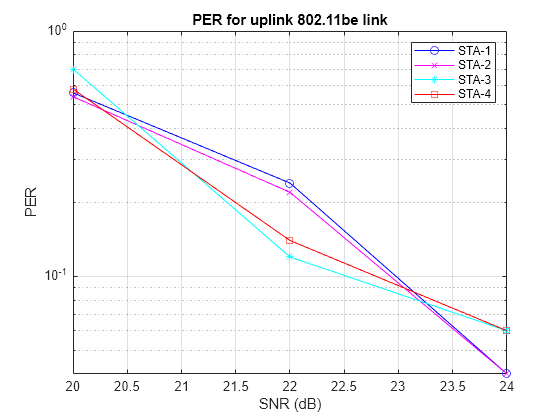
Plot Packet Error Rate vs SNR
markers = 'ox*sd^v><ph+ox*sd^v';
color = 'bmcrgbrkymcrgbrkymc';
figure;

for nSTA = 1:numUsers
    semilogy(snr,packetErrorRate(nSTA,:).',['-' markers(nSTA) color(nSTA)]);
    hold on;
end

grid on;
xlabel('SNR (dB)');
ylabel('PER');
dataStr = arrayfun(@(x)sprintf('STA-%d',x),1:numUsers,'UniformOutput',false);
legend(dataStr);
title('PER for uplink 802.11be link');
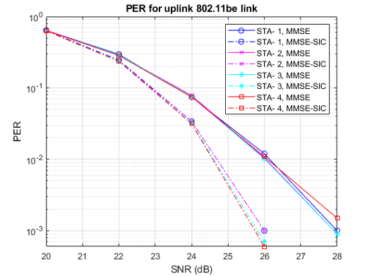
The numPackets controls the number of packets at each SNR point. For meaningful results, this value should be larger than those presented in this example. The figure below was created by running a longer simulation with numPackets:1e4 and snr:20:2:28, which shows the packet error rate of both MMSE equalizer and MMSE-SIC equalizer.
Selected Bibliography
[1] IEEE P802.11be™/D7.0. IEEE Standard for Information Technology - Telecommunications and Information Exchange between Systems - Local and Metropolitan Area Networks - Specific Requirements - Part 11: Wireless LAN Medium Access Control (MAC) and Physical Layer (PHY) Specifications - Amendment 8: Enhancements for extremely high throughput (EHT).
[2] M. Debbah, B. Muquet, M. de Courville, M. Muck, S. Simoens, and P. Loubaton. A MMSE successive interference cancellation scheme for a new adjustable hybrid spread OFDM system. IEEE 51st Vehicular Technology Conference Proceedings, pp. 745-749, vol. 2, 2000.