Packet Recovery
Received packets degrade due to radio and channel impairments. To recover packet contents, you need to perform symbol timing, estimate and correct frequency offsets, estimate the channel, and demodulate and decode the preamble and payload. WLAN Toolbox™ functions enable you to perform these operations on extremely high-throughput (EHT), high-efficiency (HE), very high-throughput (VHT), high throughput (HT), and non-HT PPDUs.
Recover EHT-Data Field from EHT SU Transmission
Generate EHT SU Waveform
Create a single-user EHT configuration object with a channel bandwidth of 320 MHz.
chanBW = "CBW320";
cfgEHTSU = wlanEHTMUConfig(chanBW);
Create an EHT recovery object with the same channel bandwidth.
cfg = wlanEHTRecoveryConfig(ChannelBandwidth=chanBW);
Create a sequence of data bits. Use the bits to generate a time-domain waveform for the specified configuration. Pass the waveform through an AWGN channel with a signal-to-noise ratio of 10 dB. Return the PPDU field indices.
bits = randi([0 1],8*psduLength(cfgEHTSU),1);
tx = wlanWaveformGenerator(bits,cfgEHTSU);
rx = awgn(tx,10);
ind = wlanFieldIndices(cfg);
Recover L-SIG Bits
Demodulate the L-LTF and estimate the channel. Using the demodulated symbols, estimate the noise power.
lltf = rx(ind.LLTF(1):ind.LLTF(2),:);
lltfDemod = wlanEHTDemodulate(lltf,"L-LTF",cfg);
lltfChanEst = wlanLLTFChannelEstimate(lltfDemod,chanBW);
nVar = wlanLLTFNoiseEstimate(lltfDemod);
Decode the L-SIG field and obtain the OFDM information. The recovery configuration object requires this information to obtain the L-SIG length.
lsig = rx(ind.LSIG(1):ind.LSIG(2));
lsigDemod = wlanEHTDemodulate(lsig,"L-SIG",cfg);
info = wlanEHTOFDMInfo("L-SIG",cfg);
lsigDemodData = lsigDemod(info.DataIndices,:);
Estimate the channel at the L-SIG field and equalize the L-SIG symbols.
preEHTChanEst = wlanPreEHTChannelEstimate(lsigDemod,lltfChanEst,chanBW);
lsigEq = wlanEHTEqualize(lsigDemodData,preEHTChanEst(info.DataIndices,:),nVar,cfg,"L-SIG");
Recover the L-SIG bits and set the L-SIG length of the recovery object.
[lsigBits,failCheck,lsigInfo] = wlanLSIGBitRecover(lsigEq,0);
cfg.LSIGLength = lsigInfo.Length;
Update Recovery Configuration Object with U-SIG Bits
Demodulate the U-SIG field.
usig = rx(ind.USIG(1):ind.USIG(2),:);
usigDemod = wlanEHTDemodulate(usig,"U-SIG",cfg);
Get the OFDM information that corresponds to the U-SIG field. Use this information to isolate the data subcarriers.
preEHTInfo = wlanEHTOFDMInfo("U-SIG",cfg);
usigDataSym = usigDemod(preEHTInfo.DataIndices,:);
Equalize the U-SIG data symbols.
x = wlanEHTEqualize(usigDataSym,preEHTChanEst(preEHTInfo.DataIndices,:),nVar,cfg,"U-SIG");Recover the U-SIG bits, ensuring that the bits pass the cyclic redundancy check (CRC).
[usigBits,failCRC] = wlanUSIGBitRecover(x,nVar);
disp(failCRC)
0 0 0 0
Update the recovery configuration object with the U-SIG bits. Display the updated object. A property value of -1 or unknown indicates an unknown or undefined property, which you can update after decoding the EHT-SIG common and user fields of the EHT SU packet.
[cfg,failInterpretation] = interpretUSIGBits(cfg,usigBits,failCRC) % This syntax does not cause an error if interpretation failscfg =
wlanEHTRecoveryConfig with properties:
ChannelBandwidth: 'CBW320'
LSIGLength: 39
CompressionMode: 1
EHTSIGMCS: 0
NumEHTSIGSymbolsSignaled: 2
LDPCExtraSymbol: -1
PreFECPaddingFactor: -1
PEDisambiguity: -1
GuardInterval: -1
EHTLTFType: -1
NumEHTLTFSymbols: -1
UplinkIndication: 0
BSSColor: 0
SpatialReuse: -1
TXOPDuration: -1
NumNonOFDMAUsers: -1
NumUsersPerContentChannel: -1
RUTotalSpaceTimeStreams: -1
RUSize: -1
RUIndex: -1
PuncturedChannelFieldValue: 0
STAID: -1
MCS: -1
ChannelCoding: unknown
Beamforming: -1
NumSpaceTimeStreams: -1
SpaceTimeStreamStartingIndex: -1
Channelization: 1
Read-only properties:
PPDUType: su
EHTDUPMode: 0
failInterpretation = logical
   0
Update Recovery Configuration Object with EHT-SIG Common Field Bits
Update the field indices with the new information from the U-SIG bits.
ind = wlanFieldIndices(cfg);
Demodulate the EHT-SIG field. Get the corresponding OFDM information.
ehtSig = rx(ind.EHTSIG(1):ind.EHTSIG(2),:);
ehtsigDemod = wlanEHTDemodulate(ehtSig,"EHT-SIG",cfg);
preEHTInfo = wlanEHTOFDMInfo("EHT-SIG",cfg);
Equalize the EHT-SIG data symbols.
x = wlanEHTEqualize(ehtsigDemod(preEHTInfo.DataIndices,:),preEHTChanEst(preEHTInfo.DataIndices,:), ...
    nVar,cfg,"EHT-SIG");
Recover and interpret the EHT-SIG common field bits.
[ehtsigCommonBits,failCRC,cfg] = wlanEHTSIGCommonBitRecover(x,nVar,cfg); % This syntax causes an error if interpretation failsUpdate Recovery Configuration Object with EHT-SIG User Field Bits
Recover and interpret the EHT-SIG user field bits. Display the updated recovery configuration object.
[ehtsigUserBits,failCRC] = wlanEHTSIGUserBitRecover(x,nVar,cfg);
cfg = interpretEHTSIGUserBits(cfg,ehtsigUserBits,failCRC); % This syntax causes an error if interpretation fails
cfg = cfg{1};
disp(cfg)
wlanEHTRecoveryConfig with properties:
ChannelBandwidth: 'CBW320'
LSIGLength: 39
CompressionMode: 1
EHTSIGMCS: 0
NumEHTSIGSymbolsSignaled: 2
LDPCExtraSymbol: 1
PreFECPaddingFactor: 3
PEDisambiguity: 0
GuardInterval: 3.2000
EHTLTFType: 4
NumEHTLTFSymbols: 1
UplinkIndication: 0
BSSColor: 0
SpatialReuse: 0
TXOPDuration: -1
NumNonOFDMAUsers: 1
NumUsersPerContentChannel: 1
RUTotalSpaceTimeStreams: 1
RUSize: 3984
RUIndex: 1
PuncturedChannelFieldValue: 0
STAID: 0
MCS: 0
ChannelCoding: ldpc
Beamforming: 0
NumSpaceTimeStreams: 1
SpaceTimeStreamStartingIndex: 1
Channelization: 1
Read-only properties:
PPDUType: su
EHTDUPMode: 0
Recover EHT-Data Field
Update the field indices with the new information from the EHT-SIG bits.
ind = wlanFieldIndices(cfg);
Demodulate the EHT-Data field and recover the bits. Verify that the recovered bits match the transmitted bits.
ehtData = rx(ind.EHTData(1):ind.EHTData(2),:);
ehtdataDemod = wlanEHTDemodulate(ehtData,"EHT-Data",cfg);
infoData = wlanEHTOFDMInfo("EHT-Data",cfg);
rxDataSym = ehtdataDemod(infoData.DataIndices,:,:);
dataBits = wlanEHTDataBitRecover(rxDataSym,nVar,cfg);
isequal(bits,dataBits)
ans = logical
   1
VHT Packet Recovery
This example shows how to recover contents from a VHT format waveform.
Generate 80 MHz VHT Waveform
Create a VHT configuration object. Set APEPLength to 3200 and MCS to 5. Create a transmission bit stream for the data field. For a VHT waveform, the data field contains PSDULength*8 bits.
cfgVHT = wlanVHTConfig(APEPLength=3200,MCS=5);
txBits = randi([0 1],cfgVHT.PSDULength*8,1);
Generate a single PPDU waveform.
txPPDU = wlanWaveformGenerator(txBits,cfgVHT);
Pass VHT Waveform Through TGac SISO Channel
Create TGac SISO and AWGN channel objects.
chBW = cfgVHT.ChannelBandwidth;
fs = 80e6;
tgac = wlanTGacChannel(SampleRate=fs,ChannelBandwidth=chBW, ...
    LargeScaleFadingEffect="Pathloss and shadowing");
awgnChan = comm.AWGNChannel(NoiseMethod="Variance",VarianceSource="Input port");
Calculate the noise variance for a receiver with a 9 dB noise figure. The noise variance, noiseVar, is equal to kTBF, where k is Boltzmann's constant, T is the ambient temperature of 290 K, B is the bandwidth (sample rate), and F is the receiver noise figure. Pass the transmitted waveform through the noisy TGac channel.
k = physconst("Boltzmann");
noiseVar = 10^((10*log10(k) + 10*log10(290) + 10*log10(fs) + 9)/10);
disp(noiseVar)
2.5443e-12
rxPPDU = awgnChan(tgac(txPPDU),noiseVar);
Recover VHT Preamble Contents from PPDU
In general, receivers process the L-STF and L-LTF to perform frequency offset estimation and correction, and symbol timing. For this example, the carrier frequency is not offset and the packet timing is 'on-time'. Therefore, for accurate demodulation, you do not need to determine the carrier frequency offset and symbol timing
Find the start and stop indices for the PPDU fields.
fieldInd = wlanFieldIndices(cfgVHT);
disp(fieldInd)
       LSTF: [1 640]
       LLTF: [641 1280]
       LSIG: [1281 1600]
    VHTSIGA: [1601 2240]
     VHTSTF: [2241 2560]
     VHTLTF: [2561 2880]
    VHTSIGB: [2881 3200]
    VHTData: [3201 12160]
The stop index of VHT-SIG-B indicates the preamble length in samples.
numSamples = fieldInd.VHTSIGB(2);
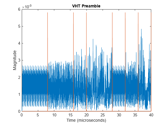
Plot the preamble and the beginning of the packet data. Add markers to the plot to show the packet field boundaries.
time = ((0:double(numSamples)-1)/fs)*1e6;
peak = 1.2*max(abs(rxPPDU(1:numSamples)));
fieldMarkers = zeros(numSamples,1);
fieldMarkers(fieldInd.LSTF(2)-1,1) = peak;
fieldMarkers(fieldInd.LLTF(2)-1,1) = peak;
fieldMarkers(fieldInd.LSIG(2)-1,1) = peak;
fieldMarkers(fieldInd.VHTSIGA(2)-1,1) = peak;
fieldMarkers(fieldInd.VHTSTF(2)-1,1) = peak;
fieldMarkers(fieldInd.VHTLTF(2)-1,1) = peak;
fieldMarkers(fieldInd.VHTSIGB(2)-1,1) = peak;
plot(time,abs(rxPPDU(1:numSamples)),time,fieldMarkers)
xlabel ("Time (microseconds)")
ylabel("Magnitude")
title("VHT Preamble")
Demodulate the L-LTF and estimate the channel.
rxLLTF = rxPPDU(fieldInd.LLTF(1):fieldInd.LLTF(2),:);
demodLLTF = wlanVHTDemodulate(rxLLTF,"L-LTF",cfgVHT);
chEstLLTF = wlanLLTFChannelEstimate(demodLLTF,cfgVHT);
Extract the L-SIG field from the received PPDU, recover its information bits, and check the CRC.
rxLSIG = rxPPDU(fieldInd.LSIG(1):fieldInd.LSIG(2),:);
symLSIG = wlanVHTDemodulate(rxLSIG,"L-SIG",cfgVHT);
trackedSymLSIG = wlanVHTTrackPilotError(symLSIG,chEstLLTF,cfgVHT,"L-SIG");
ofdmInfoLSIG = wlanVHTOFDMInfo("L-SIG",cfgVHT);
[eqSymLSIG,csiLSIG] = wlanVHTEqualize(trackedSymLSIG(ofdmInfoLSIG.DataIndices),chEstLLTF(ofdmInfoLSIG.DataIndices),noiseVar,cfgVHT,'L-SIG');
[recLSIG,failCRC] = wlanLSIGBitRecover(eqSymLSIG,noiseVar,csiLSIG);
disp(failCRC)
0
failCRC = 0 indicates that the CRC passed.
For the VHT format, the L-SIG rate bits are constant and set to [1 1 0 1]. Inspect the L-SIG rate information and confirm that this constant sequence is recovered. For the VHT format, the MCS setting in VHT-SIG-A2 determines the actual data rate.
rate = recLSIG(1:4)';
disp(rate)
1 1 0 1
Extract the VHT-SIG-A and confirm that the CRC check passed.
rxVHTSIGA = rxPPDU(fieldInd.VHTSIGA(1):fieldInd.VHTSIGA(2),:);
symVHTSIGA = wlanVHTDemodulate(rxVHTSIGA,"VHT-SIG-A",cfgVHT);
trackedSymVHTSIGA = wlanVHTTrackPilotError(symVHTSIGA,chEstLLTF,cfgVHT,"VHT-SIG-A");
[eqSymVHTSIGA,csiVHTSIGA] = wlanVHTEqualize(trackedSymVHTSIGA,chEstLLTF,noiseVar,cfgVHT,"VHT-SIG-A");
[recVHTSIGA,failCRC] = wlanVHTSIGABitRecover(eqSymVHTSIGA,noiseVar,csiVHTSIGA);
disp(failCRC)
0
Extract the MCS setting from the VHT-SIG-A. For single user VHT, the MCS is located in VHT-SIG-A2 bits 4–7.
recMCSbits = (recVHTSIGA(29:32));
recMCS = bit2int(double(recMCSbits),4,false);
disp(recMCS)
5
isequal(recMCS,cfgVHT.MCS)
ans = logical
   1
The recovered MCS setting matches the MCS value in the configuration object.
Extract and demodulate the VHT-LTF. Use the demodulated signal to perform channel estimation. Use the channel estimate to recover the VHT-SIG-B and VHT-Data fields.
rxVHTLTF = rxPPDU(fieldInd.VHTLTF(1):fieldInd.VHTLTF(2),:);
demodVHTLTF = wlanVHTDemodulate(rxVHTLTF,"VHT-LTF",cfgVHT);
chEstVHTLTF = wlanVHTLTFChannelEstimate(demodVHTLTF,cfgVHT);
Extract and recover the VHT-SIG-B.
rxVHTSIGB = rxPPDU(fieldInd.VHTSIGB(1):fieldInd.VHTSIGB(2),:);
symVHTSIGB = wlanVHTDemodulate(rxVHTSIGB,"VHT-SIG-B",cfgVHT);
trackedSymVHTSIGB = wlanVHTTrackPilotError(symVHTSIGB,chEstVHTLTF,cfgVHT,"VHT-SIG-B");
[eqSymVHTSIGB,csiVHTSIGB] = wlanVHTEqualize(trackedSymVHTSIGB,chEstVHTLTF,noiseVar,cfgVHT,"VHT-SIG-B");
recVHTSIGB = wlanVHTSIGBBitRecover(eqSymVHTSIGB,noiseVar,csiVHTSIGB,cfgVHT);
As described in IEEE Std 802.11ac-2013, Table 22-1, the value in the VHT-SIG-B Length field multiplied by 4 is the recovered APEP length for packets carrying data. Verify that the APEP length, contained in the first 19 bits of the VHT-SIG-B, corresponds to the specified APEP length.
sigbAPEPbits = recVHTSIGB(1:19);
sigbAPEPlength = bit2int(double(sigbAPEPbits),19,false)*4
sigbAPEPlength =
3200
isequal(sigbAPEPlength,cfgVHT.APEPLength)
ans = logical
   1
The recovered value matches the configured APEP Length.
Recover equalized symbols using channel estimates from the VHT-LTF.
rxVHTData = rxPPDU(fieldInd.VHTData(1):fieldInd.VHTData(2),:);
symVHTData = wlanVHTDemodulate(rxVHTData,"VHT-Data",cfgVHT);
trackedSymVHTData = wlanVHTTrackPilotError(symVHTData,chEstVHTLTF,cfgVHT,"VHT-Data");
[eqSymVHTData,csiVHTData] = wlanVHTEqualize(trackedSymVHTData,chEstVHTLTF,noiseVar,cfgVHT,"VHT-Data");
recPSDU = wlanVHTDataBitRecover(eqSymVHTData,noiseVar,csiVHTData,cfgVHT);
Compare the transmitted PSDU bits with the received PSDU bits.
numErr = biterr(txBits,recPSDU);
disp(numErr)
0
See Also
wlanEHTRecoveryConfig | wlanHERecoveryConfig