Signal Monitoring and Parameter Tuning over XCP on CAN Using Third-Party Calibration Tools
You can use XCP-based External mode simulation over CAN to connect to the Texas Instruments® C2000™ board from a third-party calibration software such as CANape and perform signal monitoring and parameter calibration. For information to configure the external mode with any available CAN module, see Set Up CAN Communication with Target Hardware.
Note
Refer to the corresponding third-party tools vendor to know more about the supported platforms.
To configure the Simulink® model for signal monitoring and parameter tuning using third-party calibration tools:
In the Simulink model, enable the signals for logging. For more information, see Save Run-Time Data from Simulation.
Identify the parameters for tuning. For more information, see Create Tunable Calibration Parameter in the Generated Code (Simulink Coder).
Open Configuration Parameters dialog box, go to the Hardware Implementation pane and select the connected Texas Instruments C2000 board from the Hardware board list.
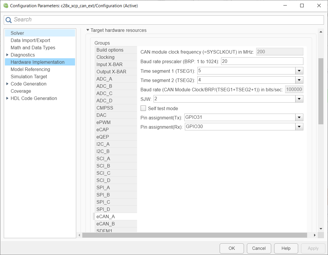
Go to Target hardware resources > CAN tab to configure different parameters related to the CAN module on the target.
Note
If the target supports multiple CAN modules, select the CAN module to be used with external mode and then configure different parameters for the selected CAN module.

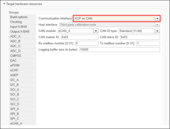
Go to Target hardware resources > External mode tab, and choose
XCP on CANas the Communication interface.Note
XCP on CANCommunication interface supports onlyThird party calibration toolsas Host interface.
Configure the CAN module on the target.
If the target supports multiple CAN modules, select the
CAN
                  module
to be used with external mode.Select the
CAN ID type.Enter the values for CAN controller ID and CAN peripheral ID.
Enter the values for Rx mailbox number and Tx mailbox number.
Enter a suitable value for Logging buffer size.
Go to Code Generation > Optimization and then set Default parameter behavior to
Inlined.Click Apply and OK.
After you configure the Simulink model, you can initiate the Build for Monitoring action in Simulink and use the A2L file that is generated, for parameter calibration using third-party calibration tools.

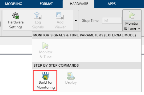
In the Hardware tab of Simulink toolstrip, click Build for Monitoring. This action builds and deploys the model on the target Texas Instruments C2000 board, and also generates an A2L file in the current MATLAB® folder path. The A2L file contains XCP peripheral information for using in third-party calibration tools. The file name of the A2L file is in this format: <modelname>
.a2l.For more information on A2L file generation, see Introduction to ASAP2 File (Simulink Coder).
Note
Monitor & Tune option is disabled during this process because
XCP on CANCommunication interface supports onlyThird party calibration toolsas Host interface.Click Deploy in the Simulink Toolstrip to deploy the executable onto the target.
Import the A2L file into third-party calibration tools, connect to the XCP peripheral, and start monitoring of signals and calibration of parameters using the interface in third-party calibration tool. For more information, refer to the example Calibrate ECU Parameters from Third-party Calibration Tools Using XCP-Based CAN Interface.
Supported Objects and Data Types
The supported objects are:
Simulink.Parameterfor parameter tuningSimulink.Signalfor signal logging
Define data objects for the signals and parameters of interest for ASAP2 file generation. For ease of use, create a MATLAB file to define the data objects so that you only have to set up the objects only once.
To set up tunable parameters and signal logging:
Associate the parameters that you want to tune with
Simulink.Parameterobjects with ‘ExportedGlobal’ storage class. It is important to set the data type and value of the parameter object. For an example of how to create such aSimulink.Parameterobject for tuning, see the following code:stepSize = Simulink.Parameter; stepSize.DataType = 'uint8'; stepSize.CoderInfo.StorageClass = 'ExportedGlobal'; stepSize.Value = 1;
Associate the signals that you want to log with
Simulink.Signalobjects. Set the data type of theSimulink.Signal. The following code example shows how to declare such aSimulink.Signalobject for logging.counter = Simulink.Signal; counter.DataType = 'uint8';Associate the data objects that you defined in the MATLAB file with parameters or signals in the model. For the previous code examples, you can set the Constant value in a Source block to
stepSize, and set a Signal name tocounterin the Signal Properties dialog box. ThestepSizeandcounterare the data objects defined in the code.
The supported data types are:
uint8, int8
uint16, int16
uint32, int32
single
Note
Logging and tuning support of 64-bit double variables is supported only on TI F2838x (C28x) board.
Limitations
Logging and tuning of 32-bit double variables is not supported. Typecast 32-bit double to single variables using Data Type Conversion blocks as logging and tuning of single variables is supported.
Logging and tuning of complex numbers is not supported. However, it is possible to work with complex numbers by breaking down the complex number into its real and imaginary components. You can perform this breakdown using the following blocks in the Simulink Math Operations library: Complex to Real-Imag, Real-Imag to Complex, Magnitude-Angle to Complex, and Complex to Magnitude-Angle.