Field-Oriented Control of an Interior Permanent Magnet Synchronous Motor
This example shows the wide-speed operation of an interior permanent magnet synchronous motor (IPMSM) drive. The drive uses a field-oriented control system with maximum torque per ampere (MTPA) and field-weakening control strategies.
Description
IPMSMs are AC synchronous motors with permanent magnets embedded in their steel rotors. Compared to the surface-mounted PMSM motors, IPMSM motors are more robust and can be operated at much higher speed. In addition, an IPMSM motor shows a relatively high magnetic saliency, which allows the motor to benefit from both the magnetic and reluctance torque components.
IPMSM motors are typically controlled using field-oriented control scheme and fed with sinusoidal currents. The example also employs flux-weakening and MTPA control schemes.
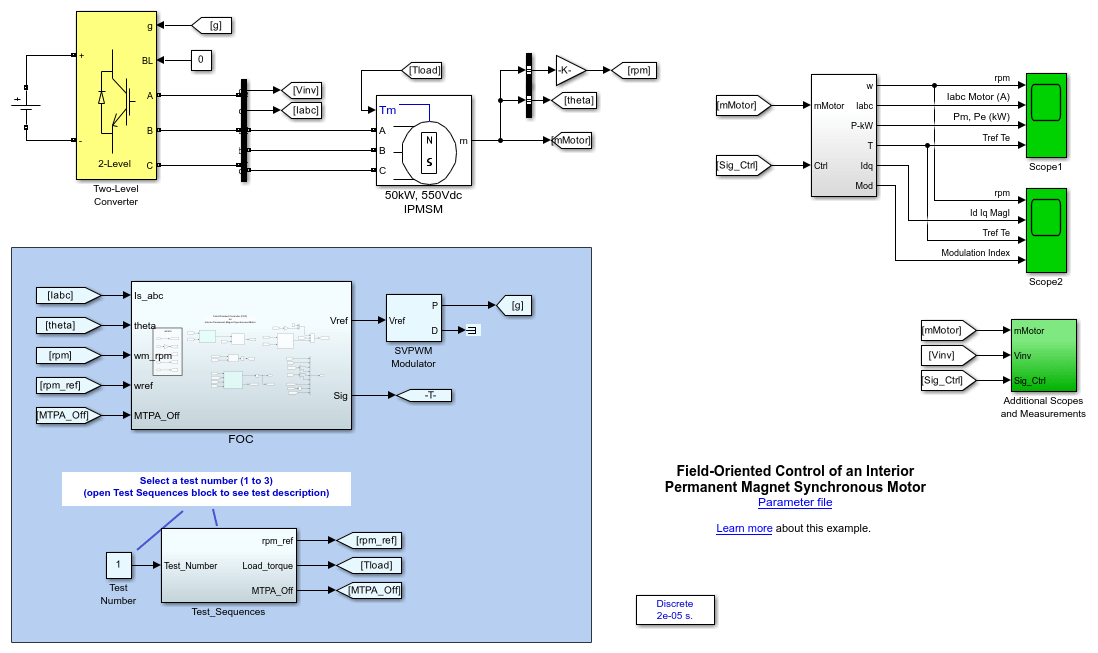
Electrical Model
A DC bus, modeled as an ideal DC source of 550 V, is connected to a three-phase, two-level converter. This converter generates the appropriate three-phase voltages (amplitude and frequency) for the speed regulation of the 50 kW IPMSM motor.
The converter is controlled by a field-oriented control (FOC) controller that generates the voltage references to a space-vector PWM modulator.
Field-Oriented Control with Field-Weakening and MTPA
FOC is a control scheme in which a d-q coordinates reference frame that is locked to the motor flux space vector is used to achieve decoupling between the motor flux and torque. Consequently, they can be separately controlled by stator direct-axis and quadrature-axis currents, respectively.
The torque is at maximum when the flux produced by the magnets is perpendicular to the stator flux produced by the stator currents. In the field-oriented control scheme, the angle between these two fluxes is maintained at 90 degrees to produce maximum torque.
The torque developed by the motor is given by:
![$$T_e = \frac{3}{2} \: p \:[ \lambda \: i_{q} + (L_{d}-L_{q})\: i_{d}\: i_{q}]$$](../../examples/simscapeelectricalsps/win64/InteriorPMSMFieldOrientedControlExample_eq17592908402323632901.png)
where
 is the number of pole pairs.
 is the flux induced by the permanent magnets in the stator windings.
 and
and  are the d-axis and q-axis inductances.
 and
and  are the d-axis and q-axis stator currents.
The equation is expressed in the rotor reference frame (the dq frame) and all quantities in the rotor reference frame are referred to the stator.
To operate the IPMSM motor at a speed higher than its nominal speed, the resulting back-EMF must be reduced in order not to exceed the maximum output voltage of the inverter. This reduction is performed by setting the d-axis stator current to a negative value to reduce the rotor flux linkage. This control strategy is called field-weakening control.
An IPMSM motor shows a relatively high magnetic saliency, which allows the motor to benefit from both the magnetic and reluctance torque components. The Maximum Torque Per Ampere MTPA algorithm calculates the d-axis and q-axis current components values to produce the desired torque while minimizing current magnitude. Additionally, the MTPA ensures that the inverter output does not saturate.
Field-Oriented Control System
The main components of the FOC system are:
Speed Regulator - The regulator compares the actual motor speed to the speed reference. If the motor needs to be accelerated, the regulator increases the reference torque magnitude (Tref) in order to create more torque. On the contrary, if the motor speed is higher than the reference, the regulator reduces Tref. This reference torque value is then fed to the Torque Limiter block to reduce the reference torque as a function of the actual speed and the torque-speed characteristics of the motor.
Current measurement d-q conversion - Based on the rotor position (represented by the signal theta in the motor model), the measured three-phase stator currents are converted into their d-q coordinates in the rotor reference frame.
Current reference calculation - Based on the reference torque
 , the actual motor speed, the estimated motor parameters, and the available supply voltage, this subsystem determines the optimized reference currents
  and Iqref using the MTPA and field-weakening algorithms.
Current Regulators - The
and the  reference currents are fed to the current regulators. The regulators process the measured and reference currents to produce the reference voltages,
  . The regulators' dynamics benefit from a feed-forward calculation of IPMSM currents based on the motor parameters.
The three-phase reference signals are connected to the PWM modulator that generates pulses for the motor inverter. The modulator uses the space vector PWM method with pulse averaging and a switching frequency of 8 kHz.
Simulation
Specify a test number in the Test Number block and run the simulation. For test 3, specify a stop time of 10 s. You can observe simulation results in both Scope 1 and Scope 2.
Test 1 : This test shows motor and generator operation in normal speed (1200 rpm) and overspeed mode (2400 rpm).
At 0.4 s, a load torque of 350 N.m. is applied to the motor. At 0.7 s, motor speed ramps to 2400 rpm and the load torque reduces to 150 N.m. The speed regulator performs well for both speed settings.
At 1.0 s, the load torque inverts from + 150 to -150 N.m so that the machine now operates as a generator.
Test 2 : This test shows the impact of the MTPA control on the motor currents. At 0.4 s, a load torque of 350 N.m. is applied to the motor. At 0.8 s, the MTPA control turns off (Idref = 0). Without the MTPA algorithm, the magnitude of the motor currents increases while producing the same torque value. This results in more stator losses. Test 3: This test shows the wide-speed operation of the IPMSM motor from 0 rpm to 6000 rpm. The motor speed ramps to 6000 rpm while the torque reference is limited in order not to exceed motor ratings and to avoid saturation of the inverter output.
Real-Time Simulation
If you have Simulink Real-Time and a Speedgoat target computer, you can run this model in real time.
Open the Configuration Parameters window (or press Ctrl+E ), click Code Generation, and set System target file to an STF for a Simulink Real-Time model.
Connect to the target and, in the Real-Time tab, click Run on Target.
Your model will then be automatically built, deployed, and executed on the target. Depending on your target streaming bandwidth, you may have to reduce the number of signals transferred in real-time from the target to the host computer.
References
Tremblay, Olivier. Development Report: Parameters estimation and vector control of internal permanent magnet synchronous machine, ETS December 2010.
Jaszczolt, Christopher. Understanding permanent magnet motors. Control Engineering. January 2017.
Cirrincione, M., M. Pucci, G. Vitale. Power Converters and AC Electrical Drives with Linear Neural Networks. CRC Press, 2012.
You can also select a web site from the following list
Americas
- América Latina (Español)
- Canada (English)
- United States (English)
Europe
- Belgium (English)
- Denmark (English)
- Deutschland (Deutsch)
- España (Español)
- Finland (English)
- France (Français)
- Ireland (English)
- Italia (Italiano)
- Luxembourg (English)
- Netherlands (English)
- Norway (English)
- Österreich (Deutsch)
- Portugal (English)
- Sweden (English)
- Switzerland
- United Kingdom (English)
Asia Pacific
- Australia (English)
- India (English)
- New Zealand (English)
- 中国
- 日本Japanese (日本語)
- 한국Korean (한국어)