PMSM 위치 제어
이 예제에서는 PMSM 기반 전기 드라이브의 회전자 위치를 제어하는 방법을 보여줍니다. 이상적 토크 소스가 부하를 제공합니다. Control 서브시스템은 2개의 제어 루프(위치 및 속도 제어를 위한 바깥쪽 루프와 전류 제어를 위한 안쪽 루프)가 있는 캐스케이드 제어 구조를 사용합니다. 추정기 설계를 위한 상태는 전자기 토크, 기계 각속도, 기계 각위치, 외란(부하 토크)입니다. 최적의 상태-피드백 선형 2차 레귤레이터가 위치와 속도를 제어합니다. Luenberger 관측기는 부하를 추정합니다. PI 제어기는 안쪽 전류 제어 루프를 구현합니다. 제어된 3상 인버터가 PMSM에 전력을 공급합니다. 시뮬레이션은 스텝 기준 신호를 사용합니다. Scopes 서브시스템은 시뮬레이션 결과를 확인할 수 있는 스코프를 포함합니다.
모델

Simscape 기록의 시뮬레이션 결과
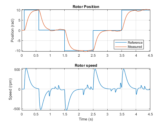
아래 플롯은 테스트에서 요청된 각도와 그 측정값을 전기 드라이브의 회전자 속도와 함께 보여줍니다.
참고 문헌
[1] S. Carpiuc and C. Villegas, "Real-time position control in permanent magnet synchronous machine drives," 2018 20th European Conference on Power Electronics and Applications (EPE'18 ECCE Europe), Riga, Latvia, 2018, pp. P.1-P.8.
참고 항목
PMSM | Converter (Three-Phase) | Luenberger Observer