Model Constant Power Consumption with Varying AC Voltage Supply
This example shows how to model constant power consumption using the Constant Power Load block in an AC circuit with varying voltage controlled by a Tap-Changing Transformer block.
Model Overview
Open the ConstantPowerLoad model.
myModel = "ConstantPowerLoad";
open_system(myModel)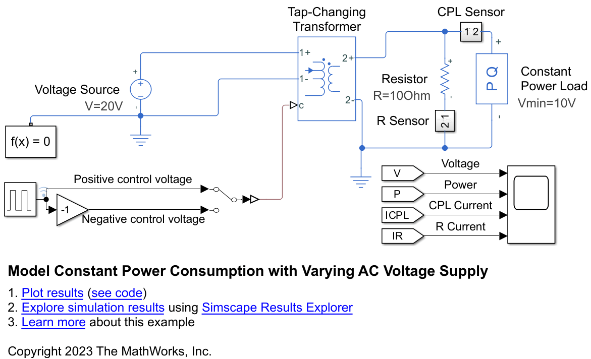
The model contains an AC circuit controlled by a tap-changing transformer. At the beginning of the simulation, the amplitude of the AC voltage is 20 V. There is no phase shift between voltage and current.
The Tap-Changing Transformer block supplies the voltage to a Constant Power Load block and a Resistor block. These blocks are connected in parallel. The Minimum Supply Voltage (RMS) parameter of the Constant Power Load block is 10 V and the Resistor block acts as a purely resistive impedance with Resistance 10 ohm. Regardless of the supply voltage, the voltage across the Resistor block and the voltage across the Constant Power Load block are always equal to each other and equal to the output of the Tap-Changing Transformer block.
Sensors measure the resulting currents through the Constant Power Load block and the Resistor block.
The value of the input to the c port of the Tap-Changing Transformer block varies periodically between 0 and 1 when you toggle the Manual Switch block to receive the Positive control voltage signal. When the signal increases above the Control threshold parameter value of the Tap-Changing Transformer block, the tap position increases by one and the voltage supplied to the Constant Power Load block increases by 15%. The Constant Power Load block operates in its constant-power regime for the entire simulation.
Conversely, when you toggle the Manual Switch block to receive the Negative control voltage signal, the input to the tap-changing transformer varies between 0 and -1. The output voltage decreases by 15% every time the signal decreases below the negative of the Control threshold parameter value. When the RMS output voltage decreases below the Minimum Supply Voltage (RMS) parameter of the Constant Power Load block, the block no longer operates in its constant-power regime and instead behaves like a resistive impedance.
Simulate Constant-Power Regime
The Constant Power Load block consumes constant power if the supplied voltage is larger than the Minimum Supply Voltage (RMS) parameter value. The amplitude describes the voltage supplied by the Voltage Source block. The Minimum Supply Voltage (RMS) parameter describes the root-mean-square of the voltage. In a steady state, these definitions differ by a factor of .
Set the Manual Switch block to receive the Positive control voltage signal. Simulate the model.
set_param("ConstantPowerLoad/Manual Switch","sw","1")
sim(myModel);
Plot the results.
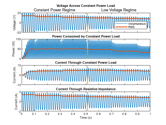
The rectangular input signals to the Tap-Changing Transformer block are positive. The resulting voltage increases every 0.2 s, starting at a time of 0.1 s.
During the first cycle, the Constant Power Load block outputs zero current while the software calculates the voltage phasor.
The Constant Power Load block consumes a nominal rated power in a steady state. The block calculates the RMS power using a harmonic approximation to calculate the power for AC voltage signals with time-dependent amplitudes. If the time scale of the amplitude change is comparable to the period of the alternating current, the instantaneous power briefly changes during the transition period.
The current through the Constant Power Load block decreases with increasing supply voltage, which results in constant power consumption. The current through the Resistor block increases with increasing supply voltage.
ConstantPowerLoadPlot

Simulate Low Voltage Regime
To simulate the behavior of the Constant Power Load block when the supply voltage is smaller than the Minimum Supply Voltage (RMS) parameter, set the Manual Switch block to receive the Negative control voltage signal. Simulate the model.
set_param("ConstantPowerLoad/Manual Switch","sw","0")
sim(myModel);
Plot the results.
The rectangular input signals to the Tap-Changing Transformer block are negative. The resulting voltage decreases every 0.2 s, starting at a time of 0.1 s. After the third tap, at a time of 0.5 s, the input voltage is lower than the Minimum Supply Voltage (RMS) parameter value.
The current through the Constant Power Load block initially increases to maintain a constant active power consumption. When the voltage from the AC supply drops below the Minimum Supply Voltage (RMS) parameter, the block models a load with constant impedance, and the current starts to decrease. The current through the Resistor block decreases with decreasing supply voltage.
ConstantPowerLoadPlot
See Also
Constant Power Load | Tap-Changing Transformer