RLC (Three-Phase)
Three-phase impedance
Libraries:
Simscape /
Electrical /
Passive /
RLC Assemblies
Description
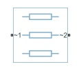
The RLC (Three-Phase) block models a three-phase impedance with two three-phase connections. Each of the three identical impedance components can include any combination of a resistor (R), capacitor (C), and inductor (L), connected in series or in parallel.
Define the values for the R, L, and C components by specifying the appropriate block parameters. Do not set the parameter values to zero or infinity to remove terms. Instead, select the correct option for the Component structure parameter.
For certain combinations of R, L, and C, for some circuit topologies, you should specify parasitic resistance or conductance values that help the simulation to converge numerically. These parasitic terms help create a small parallel resistive path for an inductor and a small series resistance for a capacitor.
Faults
Since R2024b
To model a fault in the RLC (Three-Phase) block, in the Faults section, click Add fault next to the fault that you want to model. For more information about fault modeling, see Fault Behavior Modeling and Fault Triggering.
The RLC (Three-Phase) block allows you to represent one or more faulted phases. The block models the faulted phase as a resistor. To specify the value of the faulted resistance, use the Faulted resistance parameter.
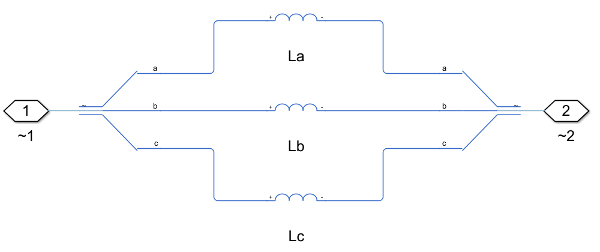
For example, this diagram shows the equivalent circuit of three-phase inductor branch.
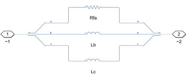
When you add a branch fault and you set the Faulted phase
parameter to Phase a, this diagram shows the equivalent
circuit of the faulted three-phase inductor branch.
Variables
To set the priority and initial target values for the block variables prior to simulation, use the Initial Targets section in the block dialog box or Property Inspector. For more information, see Set Priority and Initial Target for Block Variables.
Nominal values provide a way to specify the expected magnitude of a variable in a model. Using system scaling based on nominal values increases the simulation robustness. Nominal values can come from different sources, one of which is the Nominal Values section in the block dialog box or Property Inspector. For more information, see System Scaling by Nominal Values.
For this block, the Initial Targets and Nominal
Values settings are visible only if, in the Main
section, you do not set the Component structure parameter to
R.
Examples

Power-Loss Analysis of a Three-Phase Rectifier
Perform a power-loss analysis using the ee_getPowerLossSummary function and the power_dissipated variable. The Rectifier contains six Diode blocks. Diodes D1, D2, D4, and D5 each dissipate, on average, 52.19 W over the course of the 0.5 second simulation. Diodes D3 and D6 each dissipate an average of 52.22 W for the same time period because they experience a 340 W transient power-dissipation spike due to DC-load capacitor charging before t = 1e-3 s. For each diode, the average power dissipated when the rectifier is operating in steady-state, t = 0.4 to 0.5 s, is 52.19 W.

AC Cable with Bonded Sheaths
A three-phase cable model comprised of multiple pi-sections. Each phase is enclosed in a conductive sheath. The conductive sheath is connected to ground at either end of the cable through a simple resistance. A high-voltage source provides power to an unbalanced resistive load through the power cable. You can configure the sheath to be either series-bonded or cross-bonded. You can also configure the number of pi-sections. Increasing the number of pi-sections improves the accuracy but slows down the simulation. To facilitate convergence, the voltage source includes an internal impedance.

Comparison of Three-Phase Port Types
A comparison of Composite three-phase ports versus Expanded three-phase ports. The first circuit shows a Voltage Source configured with a Composite three-phase port. A Phase Splitter block provides the interface to the Simscape™ foundation library electrical elements. The second circuit shows a Voltage Source configured with an Expanded three-phase port which can connect directly to the Simscape foundation library electrical elements. The Voltage Source can be changed from Composite to Expanded three-phase ports by use of the Modeling option mask parameter.