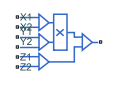
Multiplier
Integrated circuit multiplier
Libraries:
Simscape /
Electrical /
Integrated Circuits
Description
The Multiplier block models an integrated circuit multiplier. The block implements the following equation, which defines the voltage applied to the output port:
where X1, X2, Y1, Y2, Z1, Z2 are the voltages presented at the input ports, A is the gain, and K is the scale factor.
In a typical multiplication circuit, the output is fed back into input Z1, which results in the following gain (assuming that A is large):
The value of the scale factor K is usually altered by an external resistor bias network. The Multiplier block implements K as an internal gain, and the external bias network is not necessary for system simulation. A typical value for K is 10, with a typical adjustment down to 3.
You can use the Multiplier block to implement a number of other functions, as well as multiplication. Examples include division, squares, and square roots. For example circuits, see the Multiplier Integrated Circuit example or consult manufacturer data sheets. The Multiplier block behaves like a typical integrated circuit multiplier that supports up to four-quadrant multiplication and two-quadrant division. When you use a multiplier for two-quadrant division, the multiplier forms part of a feedback loop. The multiplier allows only one polarity of the denominator, either positive or negative, because reversing the denominator changes the direction of the feedback loop, which leads to instability or incorrect results. To perform two-quadrant division accurately using the Multiplier block, the denominator must be positive.
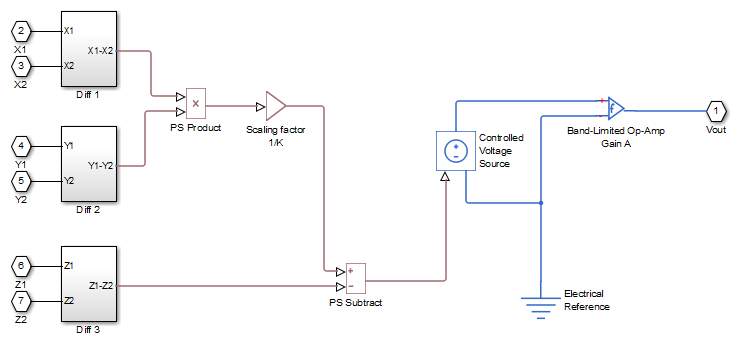
The following figure shows the internal model structure of the Multiplier block. It includes the Band-Limited Op-Amp block to model finite bandwidth and slew-rate limiting.
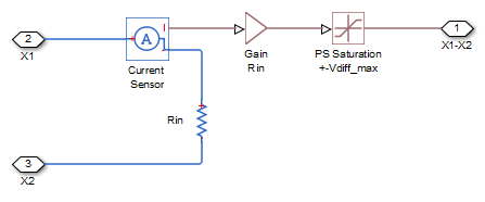
The next figure shows one of the differential subsystem blocks. All three differential subsystem blocks are identical in structure.
Examples
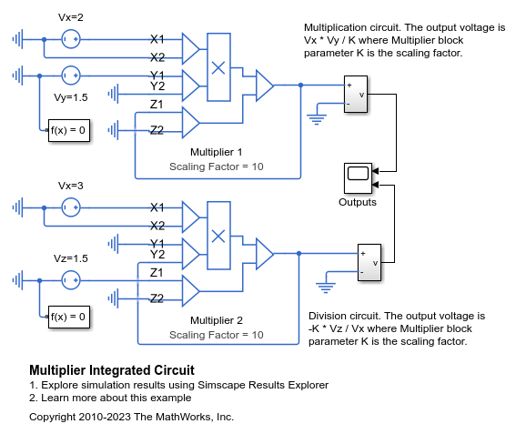
Multiplier Integrated Circuit
How the Multiplier block can be used to multiply or divide two input voltages. In both cases, slew rate limiting occurs until the final voltage is reached. Note that the input-side circuits must have an Electrical Reference block so that the solver can determine a voltage for every node.
Assumptions and Limitations
Only differential limiting of the inputs is implemented. You must ensure that the absolute values of the inputs you use keep the actual device operating in its linear region.
Output current is such that the integrated circuit is operating in the linear I-V region, which can be approximated by a voltage source plus a series output resistance.
Input offset voltage is not modeled, and the input voltage-current relationship is treated as linear within the differential signal voltage range.
Ports
Conserving
Parameters
Extended Capabilities
Version History
Introduced in R2010b